Speed control apparatus and program for speed control apparatus; and automatic vehicle driving apparatus, engine dynamo control apparatus, and control programs used for respective apparatuses

a technology of speed control apparatus and control program, which is applied in the direction of machines/engines, analogue processes, instruments, etc., can solve the problems of insufficient adverse influence of test results of analyzing exhaust gas of vehicles, and excessive increase of engine rotation number at the starting time of mt cars, etc., to improve the speed followability of actual vehicle speed, increase the and reduce the effect of initial power transmitting ra

Inactive Publication Date: 2013-07-25
HORIBA LTD
View PDF6 Cites 10 Cited by
  • Summary
  • Abstract
  • Description
  • Claims
  • Application Information

AI Technical Summary

Benefits of technology

[0042]According to the present invention as described above, as the rising commanded acceleration is increased, the initial intermediate position of the clutch comes closer to the connecting position of the clutch to increase the initial power transmitting rate, whereas as the rising commanded acceleration is decreased, the initial intermediate position comes closer to the disconnect position of the clutch to decrease the initial power transmitting rate. Accordingly, even in the case where at the starting time point, rising commanded acceleration values are different from each other, rising actual acceleration values that are approximated to the respective rising commanded acceleration values can be obtained, and therefore subsequently, at and after the starting time point, a smooth transition to the clutch feedback control can be made to drastically improve the speed followability of the actual vehicle speed with respect to the commanded vehicle speed.
[0043]Further, according to the present invention, for the respective vehicle speed and engine rotation number divisions, the correcting parameters are set, and each of the correcting parameters can be appropriately used to thereby surely reduce the engine rotation number, for example, even if the engine rotation number is unnecessarily excessively increased at the starting time of an MT car. Also, in such an occasion, the engine rotation number can also be preferably prevented from being excessively decreased to cause an engine stall or the like. Further, according to the engine dynamo control apparatus of the present invention, the engine dynamo control device can also solve a corresponding problem in the same manner.

Problems solved by technology

However, if the slip position is set to a position close to the disconnect position of the clutch, in the case where in turn, the commanded acceleration is large, a situation where the actual vehicle speed cannot sufficiently follow the commanded vehicle speed comes up immediately after the start.
This is because in the case where the engine rotation number higher than necessary is outputted, even if the vehicle can follow the running pattern, for example, a test result of analyzing exhaust gas from the vehicle is adversely influenced as compared with the case of an adequate amount of engine rotation number.
However, in practice, as a result of an experiment made by the present inventor, even in the case where the accelerator control system 104 for the starting time was configured as illustrated in FIG. 12, an engine rotation number excessively increased at the starting time of an MT car was unable to be sufficiently decreased and restored to a value close to a desired engine rotation number.
As described, the fact that reliability of the running performance map itself is low in a region where the clutch is not completely connected is considered to be one of the big reasons why the engine rotation number cannot be well controlled.
Further, at the starting time of the MT car, the engine rotation number is not only excessively increased, but instead, depending on characteristics of an engine, may be excessively decreased to stall the engine.
In such a case as well, it is difficult for the accelerator control system as illustrated in FIG. 12 to restore to the desired engine rotation number.

Method used


Image

  • Speed control apparatus and program for speed control apparatus; and automatic vehicle driving apparatus, engine dynamo control apparatus, and control programs used for respective apparatuses
  • Speed control apparatus and program for speed control apparatus; and automatic vehicle driving apparatus, engine dynamo control apparatus, and control programs used for respective apparatuses
  • Speed control apparatus and program for speed control apparatus; and automatic vehicle driving apparatus, engine dynamo control apparatus, and control programs used for respective apparatuses

Examples


first embodiment

[0068]In the following, the present invention is described with referenced to the drawings.

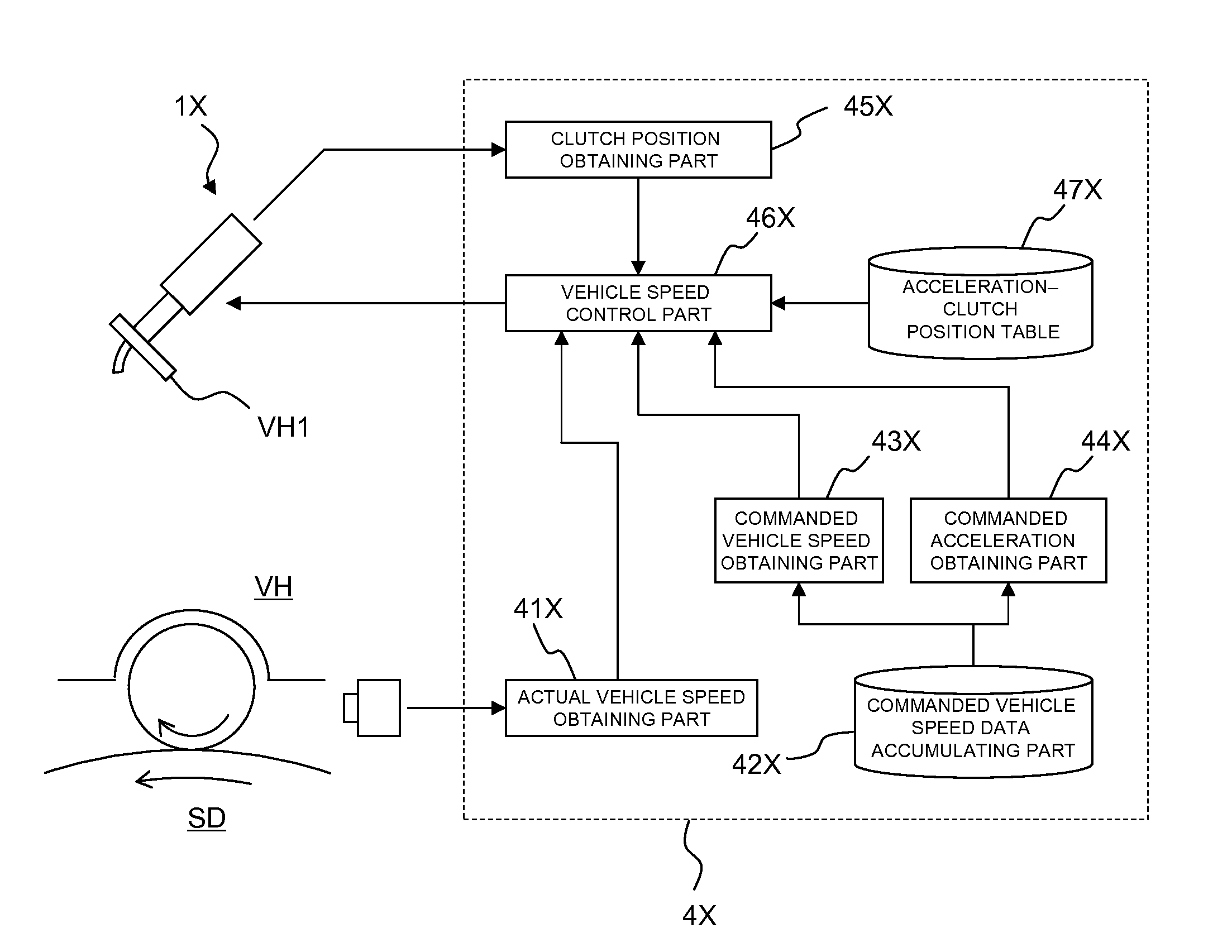
[0069]A speed control apparatus according to the first embodiment is, as illustrated in FIG. 3, one that performs speed control of an automobile VH as a vehicle placed on a chassis dynamometer SD, and is provided with: a clutch driving mechanism 1X that is arranged in a driver's seat of the automobile VH and drives a clutch; unillustrated accelerator and brake driving mechanisms that respectively drives an accelerator and a brake; and a control main body 4X that outputs control signals to the respective driving mechanisms to control a clutch position, an accelerator opening level, and a brake pushing level.

[0070]The respective parts are described.

[0071]The clutch driving mechanism 1X is provided with a cylinder member so as to be able to move a fore end part thereof backward and forward. Also, the clutch driving mechanism 1X is configured such that the fore end part is brought into abutting co...

second embodiment

[0092]Next, the present invention is described with reference to the drawings.

[0093]An automatic vehicle driving apparatus 100 of the second embodiment is one that is used in order to achieve a running pattern provided for by regulations in a running performance test for an MT car. The running performance test is performed in such a manner that, for example, as illustrated in FIG. 5, in a state where front wheels serving as drive wheels of a vehicle VH are placed on a chassis dynamometer SD, the automatic vehicle driving apparatus 100 controls an accelerator pedal VH2, a clutch pedal VH1, a brake pedal, a shift lever, and the like.

[0094]The automatic vehicle driving apparatus 100 is comprising: extendable rods that are placed on a driver's seat and respectively extend toward the clutch pedal VH1 and the accelerator pedal VH2 from the drive's seat; and a control mechanism (not illustrated) that adjusts extension amounts of the respective extendable rods with an electric motor or the ...

fourth embodiment

[0123]Next, the present invention is described with reference to FIG. 11.

[0124]In the above-described second or third embodiment, the automatic vehicle driving apparatus 100 for performing the running test on the chassis dynamometer SD is described; however, as described in the fourth embodiment, the present invention may use the apparatus as an engine dynamo control device for evaluating a single body of engine. More specifically, by configuring a throttle control system 193 that is substantially the same as the accelerator control system 102, the problem that the engine rotation number at the engine starting time is made excessively larger or smaller than a desired value can be solved.

[0125]The throttle control system 103 is, as is clear from a comparison between FIGS. 7 and 11, one that is changed with the vehicle speed, the acceleration, and the accelerator opening level being respectively made to correspond to a dynamo rotation number, a torque, and a throttle opening level, an...


PUM


Abstract

In order to further improve followability of an actual vehicle speed with respect to a commanded vehicle speed at a starting time point, the present invention is provided with a vehicle speed control part that, a predetermined time before the starting time point that is a time when the commanded vehicle speed rises from zero, sets a clutch position of a vehicle to an initial intermediate position where power is partially transmitted, and at and during a certain period of time after the starting time point, performs clutch feedback control that changes the clutch position depending on a deviation between the actual vehicle speed and the commanded vehicle speed so as to make the actual vehicle speed follow the commanded vehicle speed, wherein the vehicle speed control part sets the initial intermediate position depending on rising commanded acceleration that is a time rate of change at the time when a value of the commanded vehicle speed rises from zero.

Description

TECHNICAL FIELD[0001]The present invention relates to a vehicle control apparatus and a program for the vehicle control apparatus that, for example, perform speed control of a vehicle on a chassis dynamometer, and in particular, at the starting time point of a vehicle, control a clutch to make an actual vehicle speed of the vehicle follow a commanded vehicle speed.[0002]Also, the present invention relates to an automatic driving apparatus and automatic driving program that are intended to, in the case where a vehicle such as an automobile is run with drive wheels being placed on a rotating drum of a chassis dynamometer, and a dynamic running performance test of the vehicle is performed, automatically drive the vehicle.BACKGROUND ART[0003]This sort of speed control apparatus as described in Patent literature 1 can automatically drive a vehicle according to a predetermined running speed pattern by controlling an accelerator and brake of the vehicle. Also, an apparatus that is adapted ...

Claims


Application Information

Patent Timeline
Patent Type & Authority Applications(United States)
IPC IPC(8): G06F17/00F02D9/02
CPCG06F17/00G05D13/62F02D9/02
Inventor KONISHI, TAKAO
Owner HORIBA LTD
Why Eureka
Try Eureka