Dipper door assembly

a technology of sliding door and assembly, which is applied in the direction of mechanical machines/dredgers, soil shifting machines/dredgers, constructions, etc., can solve the problems of excessive wear, extreme abuse, and failure of existing mechanical latching mechanisms to release or latch falsely

Active Publication Date: 2013-08-01
CATERPILLAR GLOBAL MINING LLC
View PDF8 Cites 13 Cited by
  • Summary
  • Abstract
  • Description
  • Claims
  • Application Information

AI Technical Summary

Benefits of technology

[0005]An embodiment of the present disclosure relates to a dipper assembly for a mining shovel. The dipper assembly includes a dipper having a dipper back and an open dipper bottom, a dipper door coupled to the dipper for movement between an open position and a closed position, and a closure mechanism configured to retain the dipper door in the closed position. The closure mechanism includes a link having a first leg disposed adjacent the dipper back and a second leg disposed adjacent the dipper door, at least one si...

Problems solved by technology

The front wall of the dipper forms the cutting face of the dipper and is subjected to extreme abuse as the dipper cuts into the earth.
The existing mechanical latching mechanisms are subjected to false door release or failure to latch due to fou...

Method used


Image

  • Dipper door assembly
  • Dipper door assembly
  • Dipper door assembly

Examples


Embodiment Construction

[0057]Before turning to the figures, which illustrate the exemplary embodiments in detail, it should be understood that the present application is not limited to the details or methodology set forth in the description or illustrated in the figures. It should also be understood that the terminology is for the purpose of description only and should not be regarded as limiting.

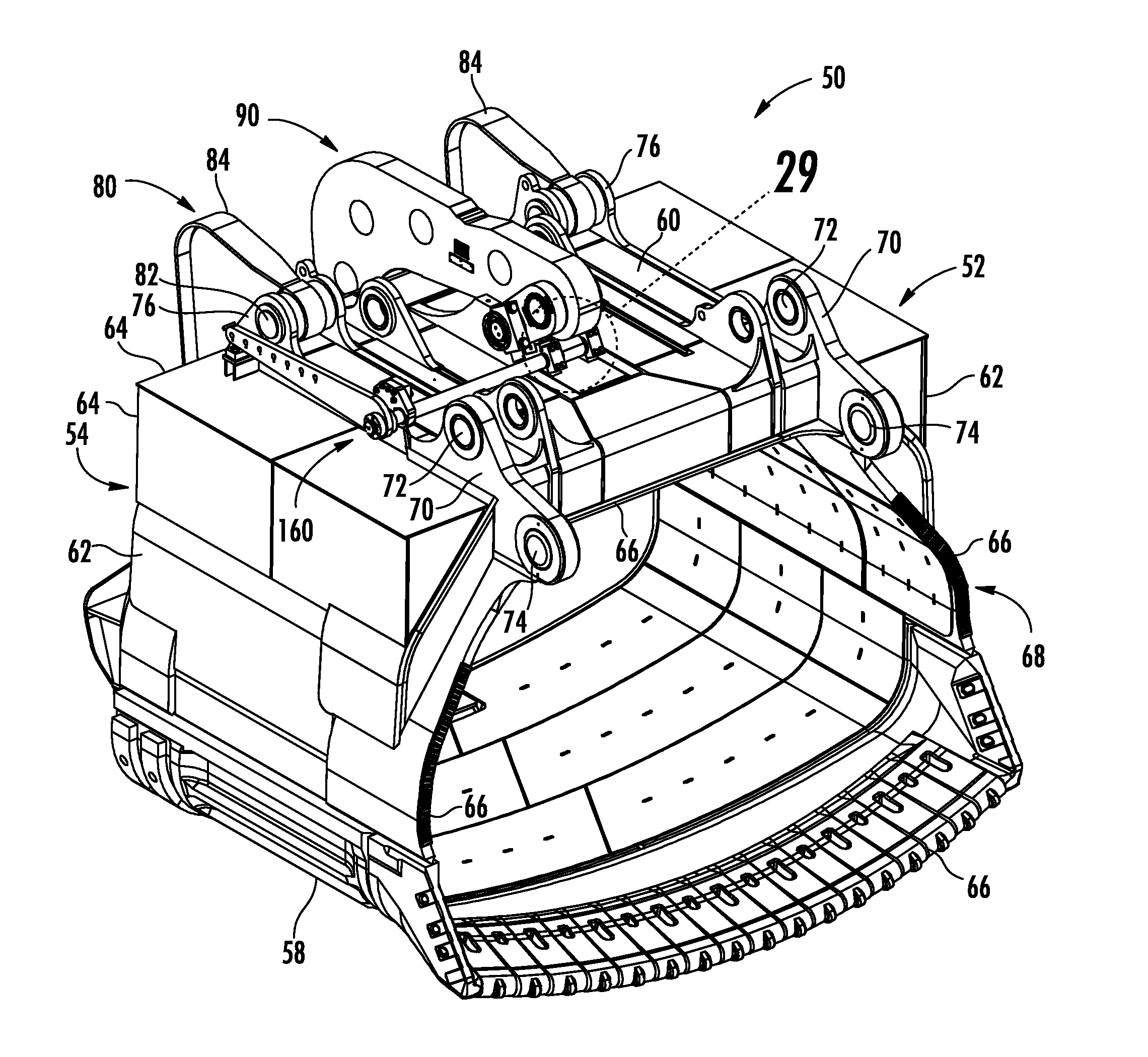
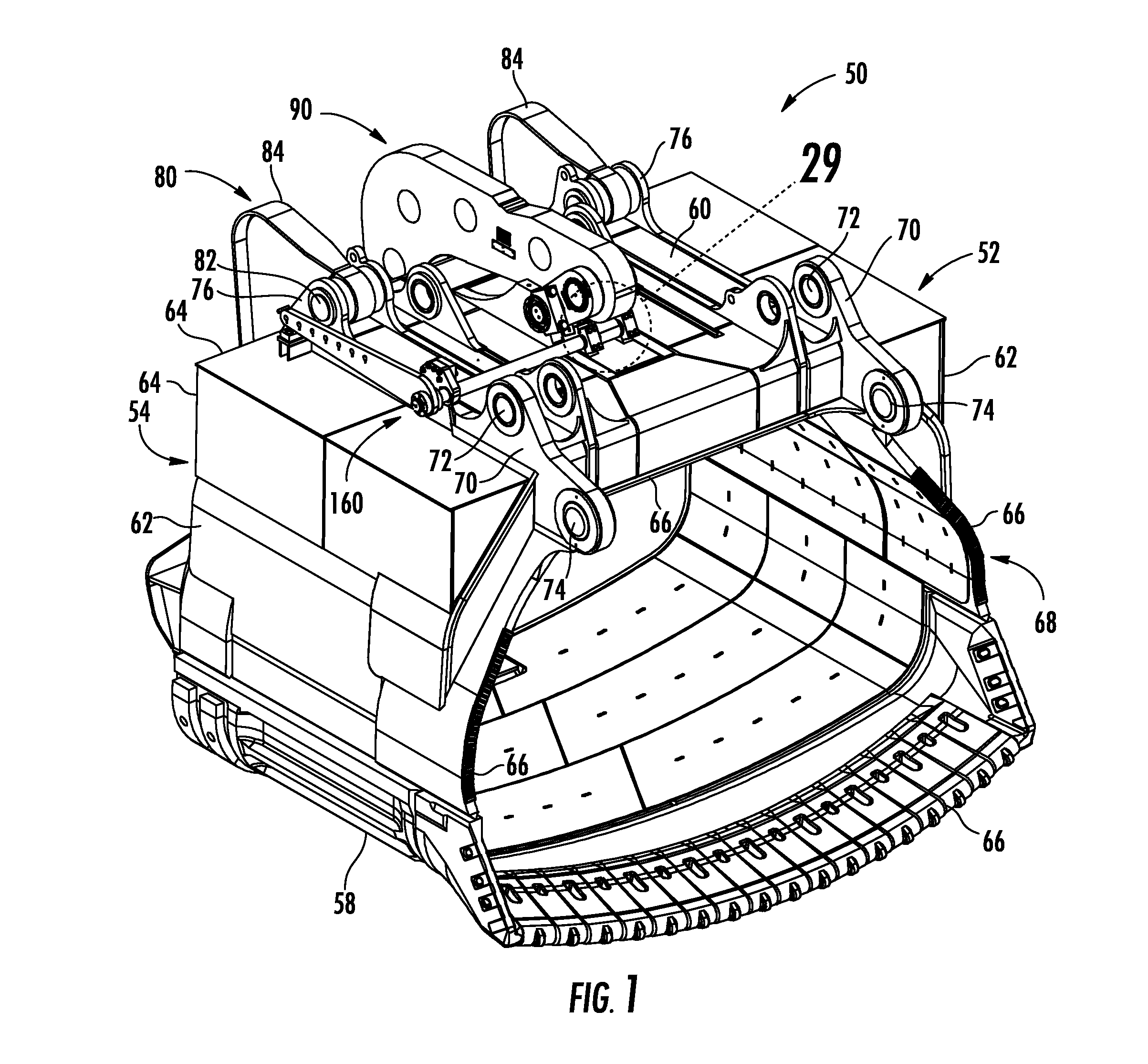
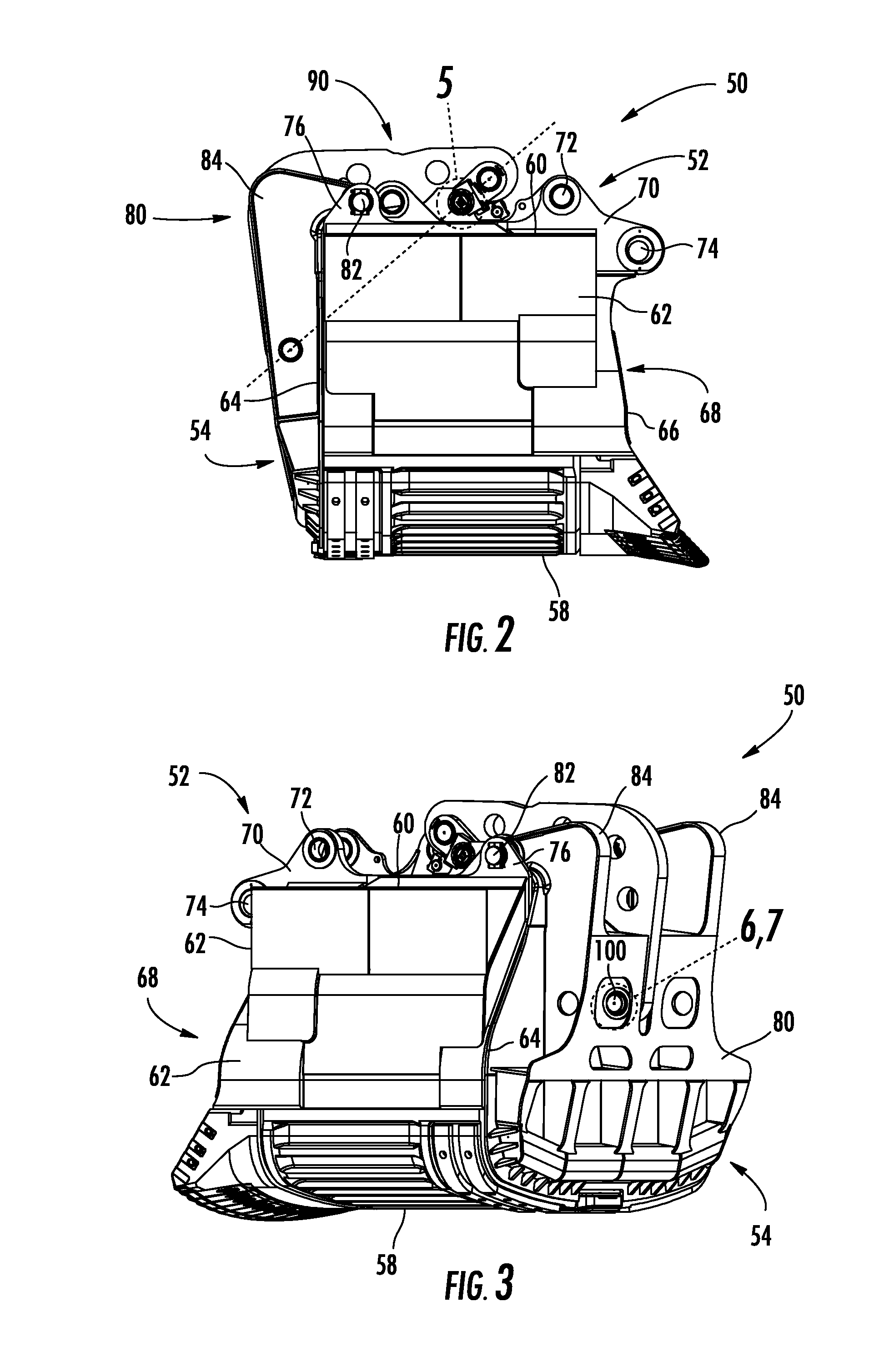
[0058]Referring to FIGS. 1-3, a dipper assembly 50 includes a dipper 52 having an open dipper bottom 54. A front wall 58 is coupled to a back wall 60 with side walls 62. Rearward edges 64 of the walls 58, 60, and 62 define the open dipper bottom 54. Forward edges 66 of the walls 58, 60, and 62 define an open forward end 68 of the dipper 52 through which the dipper 52 is filled. Teeth may be provided on the forward edge 66 of the front wall 58 to define a cutting edge that cuts into the ground to fill the dipper 52.

[0059]The open bottom 54 is closed by a pivotally mounted dipper door 80. The dipper door 80 is lock...


PUM


Abstract

A dipper assembly includes a dipper, a dipper door, a closure mechanism, and one or more block assemblies. The dipper door is pivotally mounted to the dipper, and has a closed position in which the dipper door covers the dipper bottom. The closure mechanism has a locked position and an unlocked position, and is coupled to the dipper back and the dipper door. In the locked position, the closure mechanism holds the dipper door in the closed position. In the unlocked position, the closure mechanism allows the dipper door to swing away from the closed position. The block assemblies are coupled to the dipper back and limit a rotation of the side link plate to a pre-defined angle that corresponds to the closed position.

Description

CROSS-REFERENCE TO RELATED APPLICATIONS[0001]This application claims the benefit of priority to U.S. Provisional Patent Application No. 61 / 592,266, which was filed on Jan. 30, 2012, and to U.S. Provisional Patent Application No. 61 / 697,157, which was filed on Sep. 5, 2012, the complete disclosures of which are incorporated by reference herein.TECHNICAL FIELD[0002]This disclosure relates to dippers for large mining shovels, and particularly to a dipper assembly including a closure mechanism that locks a dipper door in a closed position closing the bottom of the dipper.BACKGROUND[0003]Shovel dippers are formed with teeth at their leading edge and a dipper door that normally closes the rear of the dipper to hold earth and other materials that are loaded into the dipper by the action of the shovel. The dipper door must be held closed while the dipper is being loaded and while the load in the dipper is swung to a deposit point. At that point, the dipper door is opened to allow the conten...

Claims


Application Information

Patent Timeline
IPC IPC(8): E02F3/407
CPCE02F9/006E02F3/40E02F3/4075
Inventor GILMORE, CARL D.HOPPENS, RICHARDKLINGEL, JEFFREYMAKI, DOUGLAS E.MARJANOVIC, ZORANMEYER, KENNETH J.
Owner CATERPILLAR GLOBAL MINING LLC
Why Eureka
Try Eureka