Temperature control systems with thermoelectric devices

a technology of thermoelectric devices and temperature control systems, applied in the direction of machine operation modes, lighting and heating apparatus, heating types, etc., can solve the problems of engine not being able to heat the comfort airflow, etc., to save fuel

Inactive Publication Date: 2013-08-01
GENTHERM INC
View PDF8 Cites 57 Cited by
  • Summary
  • Abstract
  • Description
  • Claims
  • Application Information

AI Technical Summary

Benefits of technology

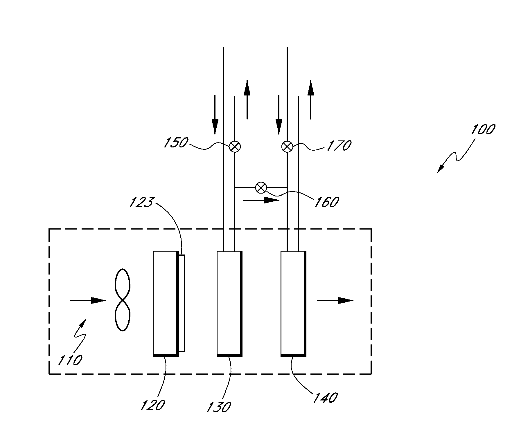
[0010]Certain disclosed embodiments include systems and methods for stopped engine or engine off heating. The engine off heating mode can be used to maintain a comfortable cabin temperature for a limited amount of time during an idle engine shutdown. The heat provided by the thermoelectric module, the thermal inertia in the coolant, and the thermal inertia in the engine block allows the system to heat the cabin of the vehicle while allowing the engine to shut down and save fuel.

Problems solved by technology

Existing automotive PTC device HVAC architectures suffer from various drawbacks.
In the startup heating mode, the thermoelectric device provides heat to the comfort airflow while the internal combustion engine is not able to heat the comfort airflow to a specified comfortable temperature without the heat provided by the thermoelectric device.
In the stop cold heating mode, the thermoelectric device provides heat to the comfort airflow while the internal combustion engine is not able to heat the comfort airflow to a specified comfortable temperature without the heat provided by the thermoelectric device.

Method used


Image

  • Temperature control systems with thermoelectric devices
  • Temperature control systems with thermoelectric devices
  • Temperature control systems with thermoelectric devices

Examples


Embodiment Construction

[0089]Although certain preferred embodiments and examples are disclosed herein, inventive subject matter extends beyond the specifically disclosed embodiments to other alternative embodiments and / or uses of the inventions, and to modifications and equivalents thereof. Thus, the scope of the inventions herein disclosed is not limited by any of the particular embodiments described below. For example, in any method or process disclosed herein, the acts or operations of the method or process may be performed in any suitable sequence and are not necessarily limited to any particular disclosed sequence.

[0090]For purposes of contrasting various embodiments with the prior art, certain aspects and advantages of these embodiments are described. Not necessarily all such aspects or advantages are achieved by any particular embodiment. Thus, for example, various embodiments may be carried out in a manner that achieves or optimizes one advantage or group of advantages as taught herein without nec...


PUM


Abstract

Temperature control systems and methods can be designed for controlling the interior climate of a vehicle or other the climate of another desired region. The temperature control system for a vehicle can have a thermoelectric system providing heating and/or cooling, including supplemental heating and/or cooling. The thermoelectric system can transfer thermal energy between a working fluid, such as liquid coolant, and comfort air upon application of electric current of a selected polarity. The thermoelectric system can supplement or replace the heat provided from an internal combustion engine or other primary heat source. The thermoelectric system can also supplement or replace cold energy provided from a compressor-based refrigeration system or other primary cold energy source.

Description

INCORPORATION BY REFERENCE TO ANY PRIORITY APPLICATIONS[0001]Any and all applications for which a foreign or domestic priority claim is identified in the Application Data Sheet as filed with the present application, are incorporated by reference and made a part of this specification.BACKGROUND[0002]1. Field[0003]This disclosure relates to the field of temperature control and to temperature control systems and methods incorporating a thermoelectric device.[0004]2. Description of Related Art[0005]A passenger compartment of a vehicle is typically heated and cooled by a heating, ventilating, and air conditioning (HVAC) system. The HVAC system directs a flow of comfort air through a heat exchanger to heat or cool the comfort air prior to flowing into the passenger compartment. In the heat exchanger, energy is transferred between the comfort air and a coolant such as a water-glycol coolant, for example. The comfort air can be supplied from ambient air or a mixture of air re-circulated fro...

Claims


Application Information

Patent Timeline
Patent Type & Authority Applications(United States)
IPC IPC(8): F25B21/04
CPCF25B21/04B60H1/00478F24F5/0042B60H1/034B60H1/00885F25B2321/021B60H1/00778H10N10/13B60H1/00835B60H2001/00128B60H2001/00135
Inventor BARNHART, TODD ROBERTRANALLI, MARCOADLDINGER, MARTIN
Owner GENTHERM INC
Why Eureka
Try Eureka