Oven convection fan

a convection fan and oven technology, applied in the field of convection fans, can solve the problems of difficult to match the size of the built-in oven, the cost of closed loop control system components necessary to operate in the harsh high temperature environment of the oven, and the difficulty of achieving the effect of efficient air flow, low cost and maximum useful spa

Inactive Publication Date: 2013-08-01
CHANG DARWIN +1
View PDF16 Cites 8 Cited by
  • Summary
  • Abstract
  • Description
  • Claims
  • Application Information

AI Technical Summary

Benefits of technology

[0017]A number of novel methods of locating the convection fan within the oven help to maximize useful space. The design of the fan is improved to produce more efficient air flow in low cost production methods. Some designs of the fan incorporate novel sources of power such as using the pre-existing oven light bulb socket and the pre-existing oven light switch.

Problems solved by technology

Built-in ovens are often hard to match in size, color, style and require a licensed contractor to handle the electrical power connections.
Thus, ovens last a long time.
Previous to this invention, the closed loop control system components necessary to operate in the harsh high temperature environment of an oven were expensive relative to the cost of a consumer oven or consumer oven accessory item.
These devices are limited in ability and do not offer an air moving device and the related benefits.
These devices occupy additional counter space and lack the performance of a full size oven.
The exteriors are generally hotter, the insulation is poorer and the efficiency is low when compared to a conventional oven.
These room temperature devices are unable to operate in the sustained high temperature environment found in or around a hot oven.
Paper parts would burn.
Electrical insulation on wires and particularly motor windings would fail.
Energy source devices such as batteries might even explode.

Method used


Image

  • Oven convection fan
  • Oven convection fan
  • Oven convection fan

Examples


Embodiment Construction

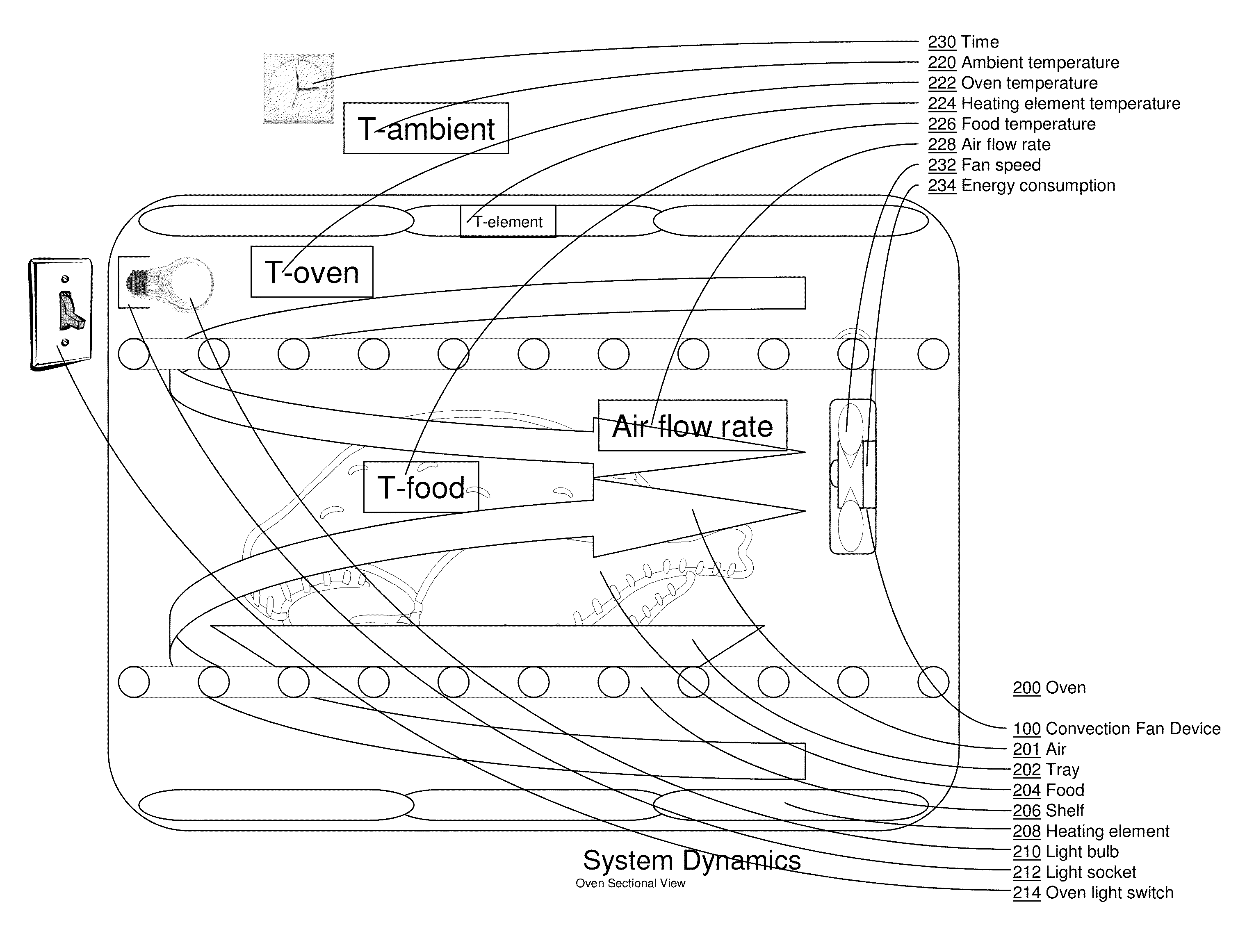
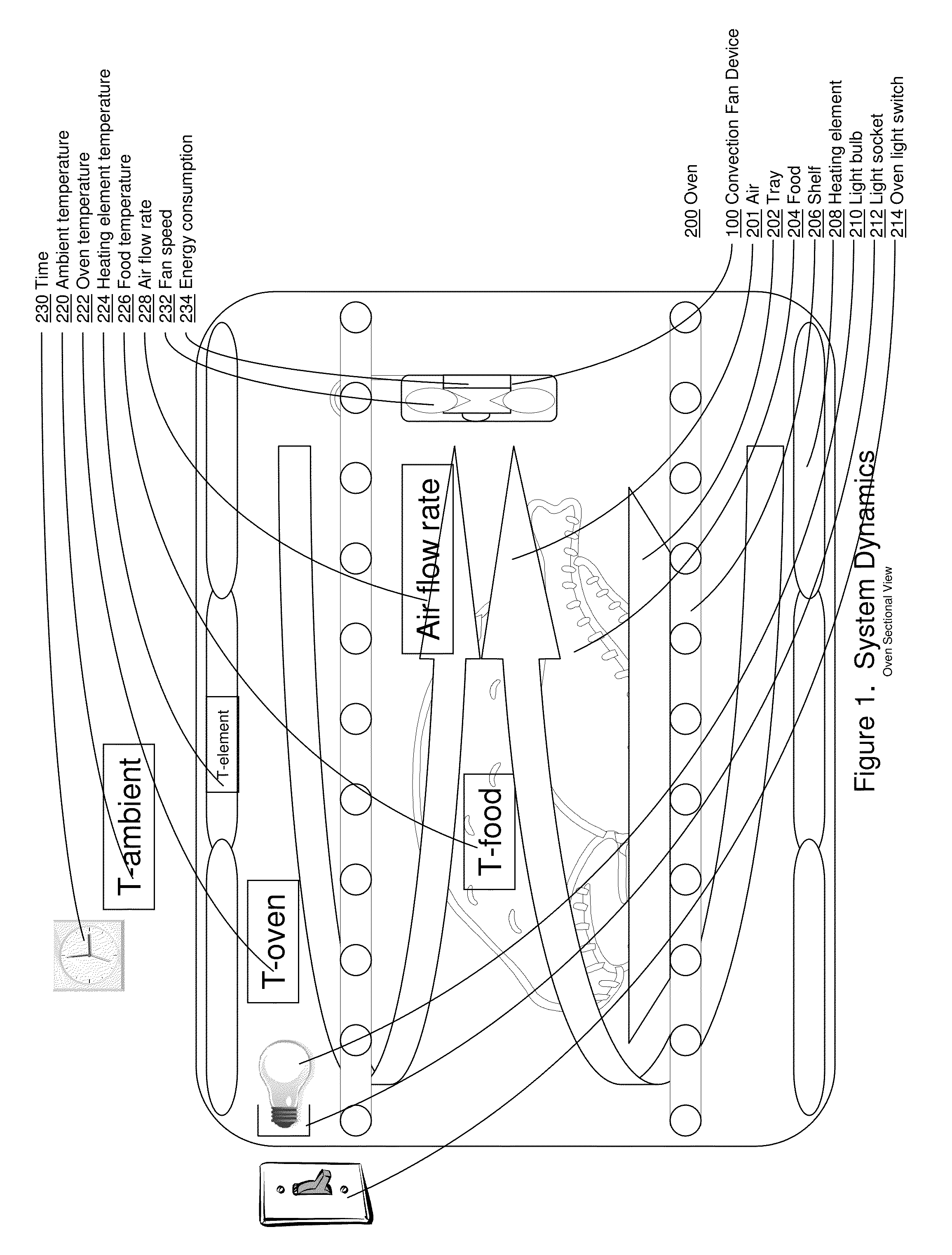
[0033]Described herein are exemplary systems and methods for an oven convection fan device. In the following description, numerous specific details are set forth to provide a thorough understanding of various embodiments. However, it will be understood by those skilled in the art that the various embodiments may be practiced without the specific details. In other instances, well known methods, procedures, components, and circuits have not been illustrated or described in detail so as not to obscure the particular embodiments.

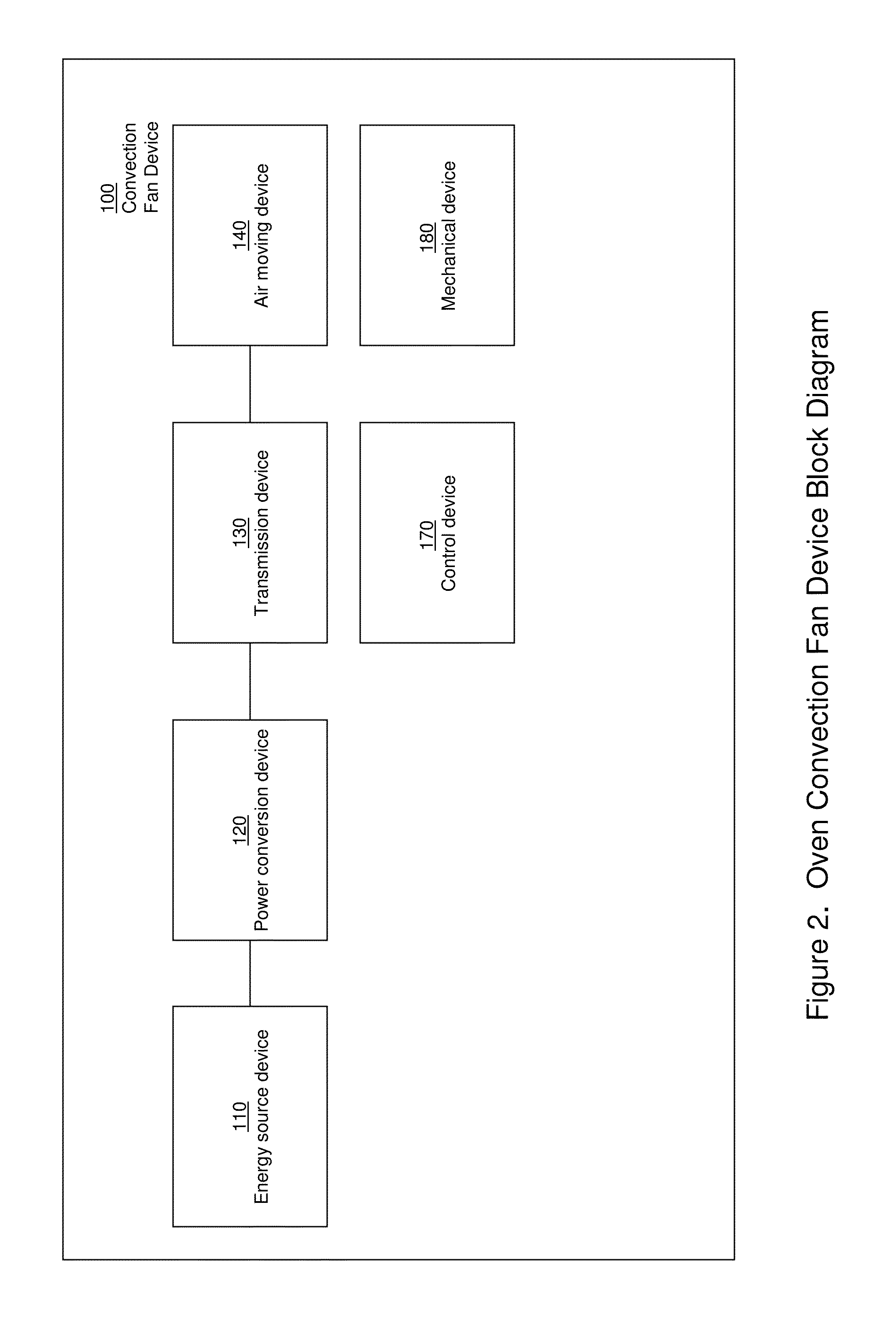
[0034]The term “air moving device” includes but is not limited to turbines, propellers, impellers, blades, wings, blowers, pumps, compressors, rotating or non-rotational air moving devices, piezo electric vibrating devices, MEMS (Micro Electro Mechanical System), explosive devices, pressure difference generating devices, temperature difference generating devices, velocity difference generating devices, mass difference generating devices, arrays of air moving dev...


PUM


Abstract

A high temperature convection fan device that improves the operation of an oven is provided. Each oven convection fan device component is designed to withstand the harsh environment and elevated temperatures common to an oven. Sources of energy include but are not limited to wind-up springs and/or drawing electric power from the oven lamp socket. Other solutions provide additional features including but not limited to lighting, sensors, control systems and/or displays.

Description

BACKGROUND OF THE INVENTION[0001]1. Field of the Invention[0002]Embodiments of the present invention generally relate to a convection fan for ovens. More specifically, embodiments of the present invention relate to an after market device that can be incorporated in an ordinary oven to improve performance.[0003]2. Description of the Related Art[0004]As people become more aware of rising energy costs and environmental concerns, there is an opportunity to improve the efficiency of appliances and in particular household kitchen ovens. For new construction, renovations and replacements, consumers have the choice to upgrade the oven to a convection oven with a built-in convection fan. Consider that repairing an oven is common since replacement oven parts are widely available, inexpensive and easy to replace. Built-in ovens are often hard to match in size, color, style and require a licensed contractor to handle the electrical power connections. Thus, ovens last a long time.[0005]This inve...

Claims


Application Information

Patent Timeline
Patent Type & Authority Applications(United States)
IPC IPC(8): F24C15/00
CPCF24C15/00F24C15/322F24C15/008
Inventor CHANG, DARWINTONG, HING S.
Owner CHANG DARWIN
Why Eureka
Try Eureka