Balanced flow dialysis machine

a dialysis machine and flow-balance technology, applied in the field of medical fluid treatment, can solve the problems of insufficient convective clearance, difficulty in installing and using components, and the need for dedicated water treatment, so as to enhance the clearance of waste products from the renal patient, increase the volume of dialysate, and enhance the effect of waste clearan

Active Publication Date: 2013-08-01
BAXTER INT INC +1
View PDF9 Cites 70 Cited by
  • Summary
  • Abstract
  • Description
  • Claims
  • Application Information

AI Technical Summary

Benefits of technology

[0011]Air bubble detectors, heating elements, pressure sensors, temperature sensors, etc. are also integrated into the cassette for both the dialysate management and extracorporeal blood sides as necessary to allow for a safe treatment for the patient and reliable operation of the system.
[0026]A third type balancing device is one or more torturous paths. The torturous path is defined in one embodiment by a disposable cassette as an elongated channel. The diameter or cross-sectional area of the channel is configured so that bulk movement of fresh or effluent dialysate can efficiently move an existing bulk of fluid within the torturous path. That is, fresh dialysate in bulk moves a bulk of spent or effluent dialysate currently residing in the path to drain. In the next cycle, spent or effluent dialysate in bulk pushes the bulk of fresh fluid just introduced into the torturous path to the patient or dialyzer. The cross-section and the length of the path are configured to minimize an amount of mixing of the fresh and spent fluids at the ends of the bulks of fluid.

Problems solved by technology

That substitution fluid and the fluid accumulated by the patient in between treatments is ultrafiltered over the course of the HF treatment, providing a convective transport mechanism that is particularly beneficial in removing middle and large molecules (in hemodialysis there is a small amount of waste removed along with the fluid gained between dialysis sessions, however, the solute drag from the removal of that ultrafiltrate is not enough to provide convective clearance).
One of the drawbacks of home hemodialysis is the need for a dedicated water treatment, which includes equipment, water connection and drainage.
Installing and using those components is a difficult and cumbersome task that can require a patient's home to be modified.
Due to the impracticality of hanging and storing bags, solution-bag based systems are limited to a total practical amount of dialysate per treatment.

Method used


Image

  • Balanced flow dialysis machine
  • Balanced flow dialysis machine
  • Balanced flow dialysis machine

Examples


example

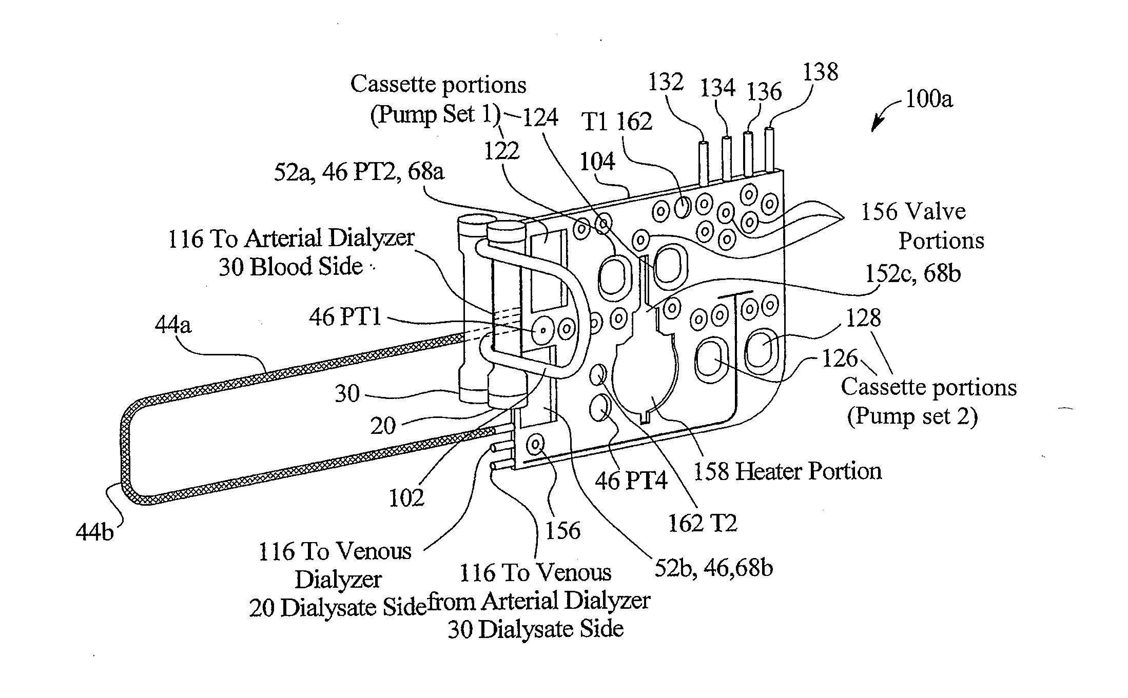
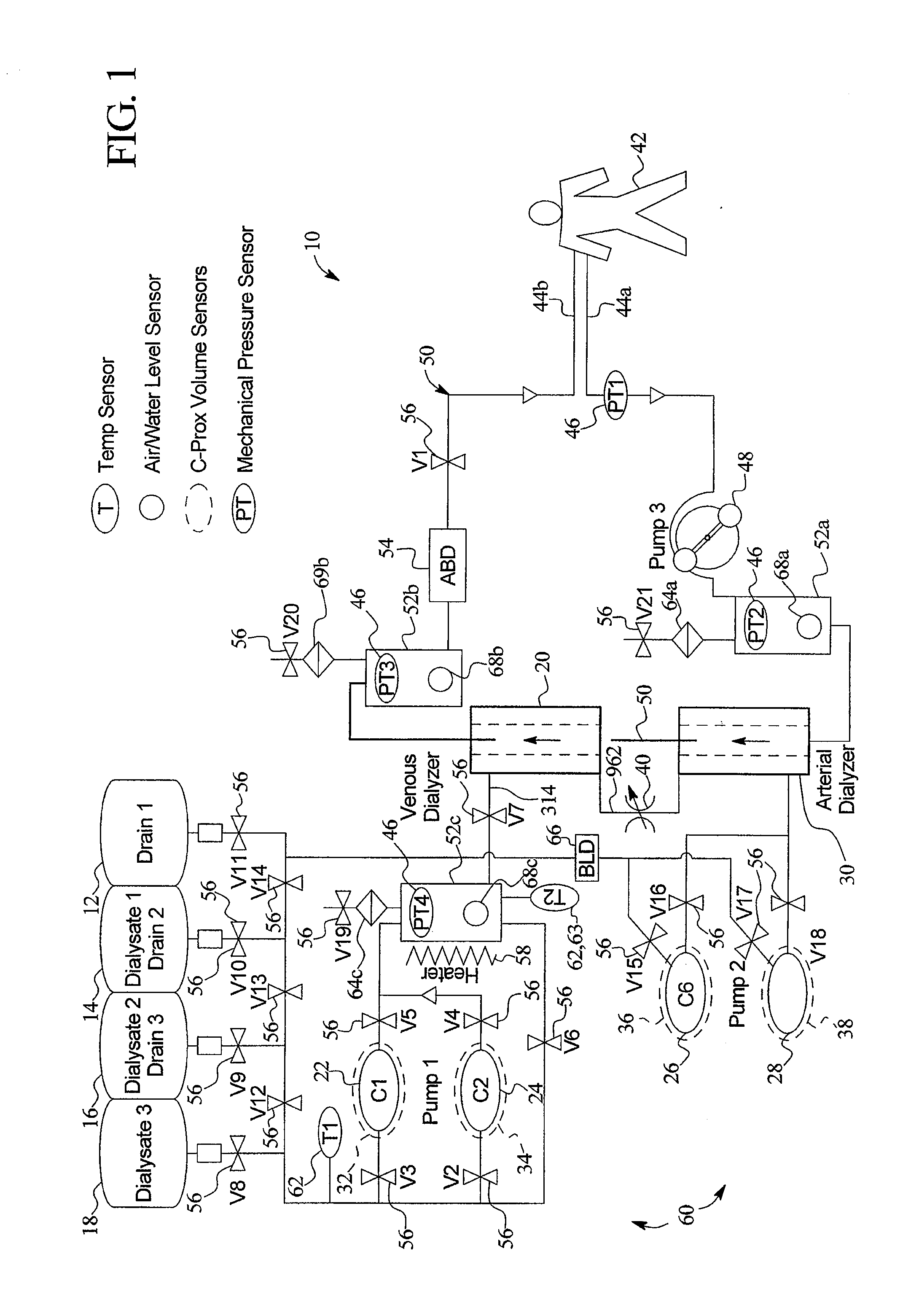
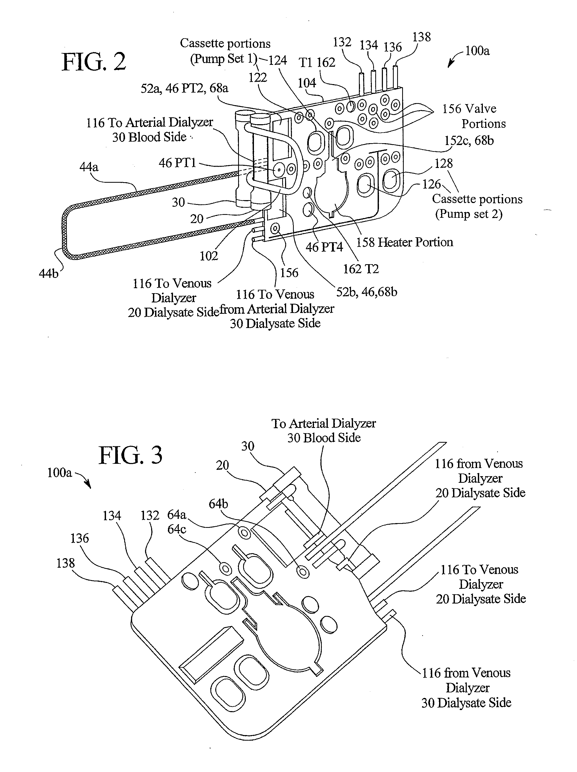
[0113]The following example further illustrates one preferred therapy for the present invention. In the example, pumps 22 and 24 of Pump Set 1 infuse eighteen liters of dialysate from sources 14, 16 and 18 over two hours. Of that volume, one hundred ml / min of dialysate is backfiltered into the patients' blood circuit 50 through the membrane walls of venous dialyzer 20. Fifty ml / min of dialysate passes through the venous dialyzer 20, restriction 40 and into venous dialyzer 30. Pumps 26 and 28 of Pump Set 2 remove the total of eighteen liters of dialysate from bags 14, 16 and 18 plus any desired amount of fluid from the patient. Over two hours, twelve liters (100 ml / min multiplied by 120 minutes) of dialysate is backfiltered into the patient's blood through the venous dialyzer 20. Pumps 26 and 28 of Pump Set 2 remove that twelve liters, the six liters of dialysate that is not backfiltered into blood circuit 50 plus any fluid ultrafiltered from the patient.

[0114]The addition and remova...


PUM

PropertyMeasurementUnit
volumeaaaaaaaaaa
surface areaaaaaaaaaaa
dielectric constantaaaaaaaaaa

Abstract

A system and method for balancing flows of renal replacement fluid is disclosed. The method uses pressure controls and pressure sensing devices to more precisely meter and balance the flow of fresh dialysate and spent dialysate. The balancing system may use one or two balancing devices, such as a balance tube, a tortuous path, or a balance chamber.

Description

PRIORITY CLAIM[0001]This application is a continuation application of, and claims the benefit of and priority to, U.S. patent application Ser. No. 11 / 938,083, filed on Nov. 9, 2007, the entire contents of which are incorporated herein by reference.BACKGROUND OF THE INVENTION[0002]The present invention relates generally to medical treatments. More specifically, the present invention relates to medical fluid treatments, such as the treatment of renal failure and fluid removal for congestive heart failure.[0003]Hemodialysis (“HD”) in general uses diffusion to remove waste products from a patient's blood. A diffusive gradient that occurs across the semi-permeable dialyzer between the blood and an electrolyte solution called dialysate causes diffusion. Hemofiltration (“HF”) is an alternative renal replacement therapy that relies on a convective transport of toxins from the patient's blood. This therapy is accomplished by adding substitution or replacement fluid to the extracorporeal circ...

Claims


Application Information

Patent Timeline
Patent Type & Authority Applications(United States)
IPC IPC(8): A61M1/16
CPCA61M1/16A61M1/1696A61M1/28A61M1/3413A61M1/3427A61M2205/12A61M1/1635A61M1/3417A61M1/342A61M1/3441A61M1/3434A61M1/3437A61M1/3444A61M1/3458A61M1/3465A61M1/3468A61M1/166A61M1/284A61M1/288A61M2205/3331A61M2205/3393A61M1/1605A61M1/1613A61M1/341A61M2205/3368A61M2205/3334A61M1/155A61M1/154A61M1/15625A61M1/362223A61M1/362262A61M1/362264A61M1/1522A61M1/15632A61M1/362261A61M1/1561A61M1/1565A61M1/362265A61M1/3401A61M1/153A61M1/36224A61M1/14
Inventor HOGARD, MICHAEL E.BUSBY, DONALD D.CHILDERS, ROBERT W.DING, YUANPANG SAMUELHOLIAN, KATHERINE M.JABLONSKI, MARK E.KELLY, THOMAS D.LO, YING-CHENGMALIEKKAL, SHINCY J.ROGER, RODOLFO G.SMITH, DONALD A.YARDIMCI, ATIF M.
Owner BAXTER INT INC
Why Eureka
Try Eureka