Identification and communication system for inflatable devices

a technology of identification and communication system, which is applied in the field of pneumatic systems, can solve the problems of not being able to distinguish between different articles to be inflated or different pumps, and the connectors that prevent re-use are not able to distinguish between different articles to be inflated, so as to prevent inadvertent and unsafe operation, safe and effective therapy

Inactive Publication Date: 2008-07-15
HUNTLEIGH TECH LTD
View PDF26 Cites 37 Cited by
  • Summary
  • Abstract
  • Description
  • Claims
  • Application Information

AI Technical Summary

Benefits of technology

[0029]In a healthcare environment this use of communication means prevents the inadvertent and unsafe operation of pump types with inflatable garments or supports e.g. pads or mattresses, which are not functionally safe or clinically compatible. A pump equipped with the communication means will readily deliver safe, effective therapy with a wide range of such inflatable articles.

Problems solved by technology

However, such pneumatic systems of the prior art including connectors that prevent re-use are not able to distinguish between different articles to be inflated or different pumps.

Method used


Image

  • Identification and communication system for inflatable devices
  • Identification and communication system for inflatable devices
  • Identification and communication system for inflatable devices

Examples


Embodiment Construction

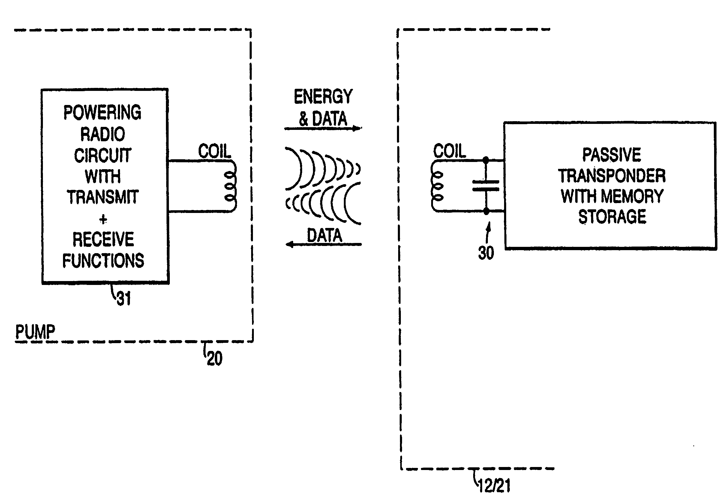
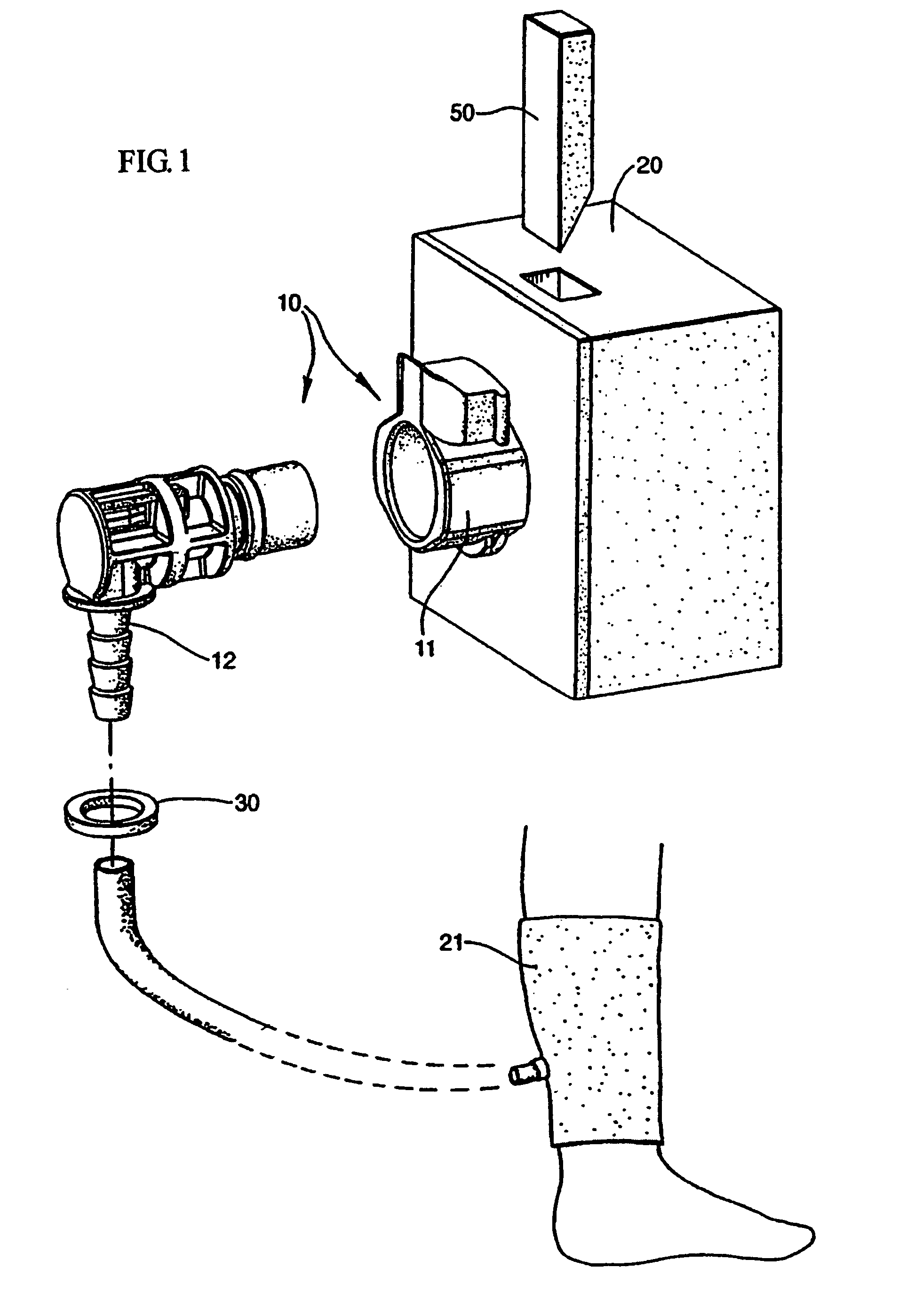
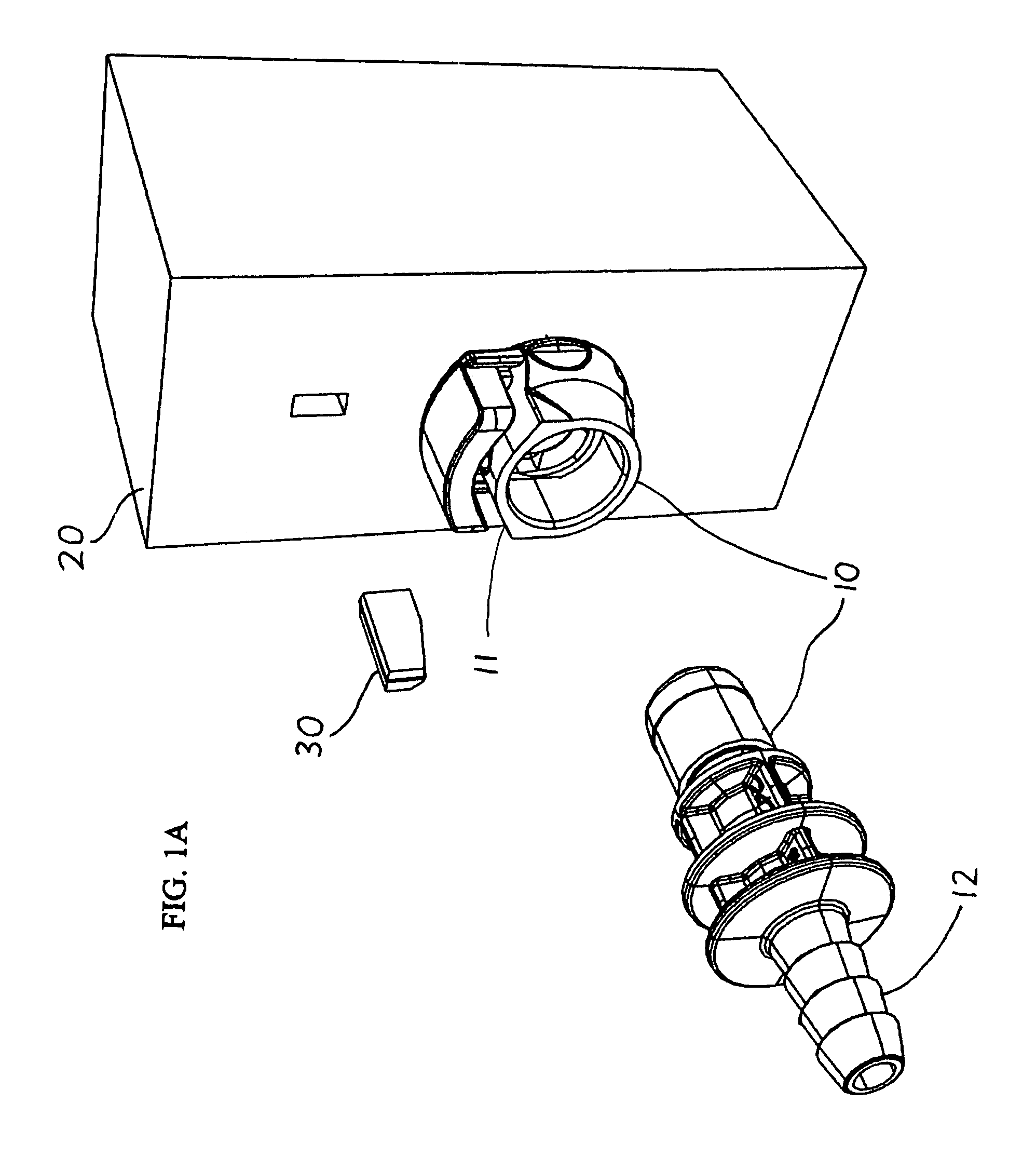
[0041]Referring to FIG. 1, the preferred embodiment consists of a pneumatic system consisting of a compression garment 21 connected to a pump 20 by a connector 10. The connector 10 has a connector part 11 connected to the pump 20 and a cooperating connector part 12 connected to the fluid line of the garment 21. The connector 12 carries a radio frequency identification device 30, i.e. a transponder (FIG. 2). The transponder 30 is mounted on the connector part 12 connecting the compression garment 21 to the pump 20 and a corresponding radio circuit is located within the pump 20. The transponder 30 may be in the shape of an annular ring fitted to the connector part 12 surrounding its fluid line outlet or any suitable shape to fit on or adjacent the connector 12. The transponder 30 typically comprises a coil 32 acting as an antennae to transmit and receive signals, a capacitor to temporarily store energy to power the transponder, an integrated circuit to provide control and modulation f...


PUM

PropertyMeasurementUnit
phase changeaaaaaaaaaa
energyaaaaaaaaaa
sizeaaaaaaaaaa

Abstract

A pneumatic system consists of an inflatable/deflatable article, for example, a compression garment connected to a pump by connectors, respectively. The connector attached to the garment carries an RFID transponder and a corresponding radio circuit is located within the pump. In use, the transponder transmits and receives information to and from the pump radio circuit. The information exchanged is used by the pump control system to activate the pump and to operate the pump to provide the particular operating parameters for that garment, for example, pressure, inflation/deflation cycle duration of treatment, etc. The pneumatic system may include communication means for the pump, such as a radio circuit, that is located remote from the pump. Also, the pneumatic system may include a support mechanism that functions both as a handle and a hook.

Description

CROSS-REFERENCE TO RELATED APPLICATIONS[0001]This application claims priority to and is a continuation-in-part of U.S. application Ser. No. 09 / 509,265, entitled “IDENTIFICATION AND COMMUNICATION SYSTEM FOR INFLATABLE DEVICES”, filed Jul. 25, 2000, now U.S. Pat. No. 6,884,255, which was the National Stage of and claims priority to International Application No. PCT / GB99 / 02403, filed Jul. 23, 1999, which claims priority to Great Britain Application No. 9816173.0, filed Jul. 25, 1998; this application claims priority to all three previous applications. The aforementioned U.S. application is hereby incorporated by reference in its entirety into this application.COPYRIGHT NOTICE[0002]A portion of the disclosure of this patent document contains material which is subject to copyright protection. The copyright owner has no objection to the facsimile reproduction by anyone of the patent document or the patent disclosure, as it appears in the Patent and Trademark Office patent files or records...

Claims


Application Information

Patent Timeline
Patent Type & Authority Patents(United States)
IPC IPC(8): B65B1/30A47C27/08A61H23/04B60S5/04F04B49/06G06K19/07
CPCA61H9/0078G06K19/0723F04B49/065B60S5/046
Inventor NEWTON, MICHAEL DAVID
Owner HUNTLEIGH TECH LTD
Why Eureka
Try Eureka