Projectile target system

a projectile target and target technology, applied in the field of projectile targets, can solve the problems of lack of shot detection accuracy, lack of reliability, and simple two-dimensional detector on or over the target face, and achieve the effect of accurately determining the impact location of a projectile, increasing the computational load on the target controller, and increasing the accuracy

Inactive Publication Date: 2013-08-01
HEX SYST
View PDF14 Cites 60 Cited by
  • Summary
  • Abstract
  • Description
  • Claims
  • Application Information

AI Technical Summary

Benefits of technology

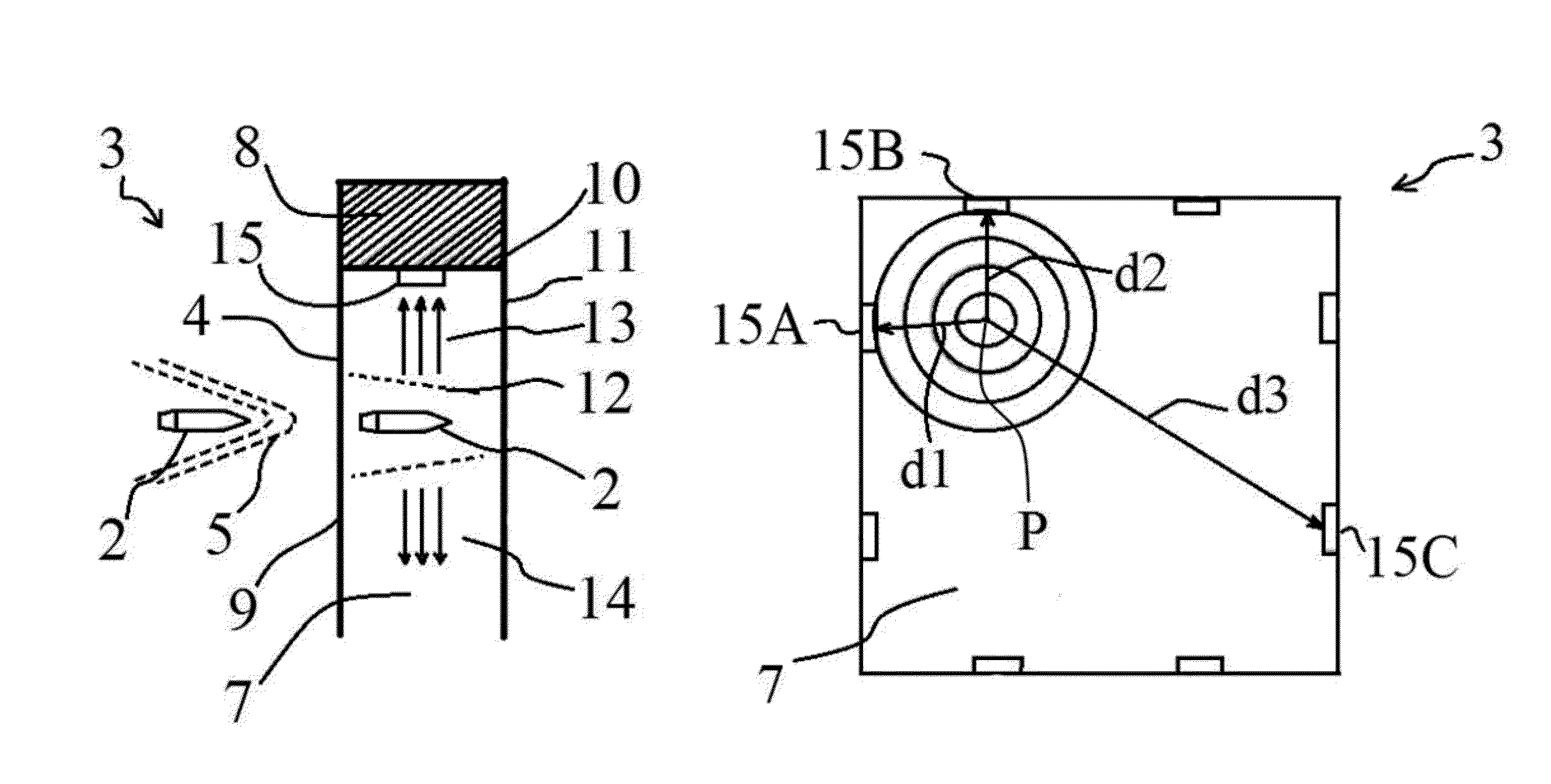
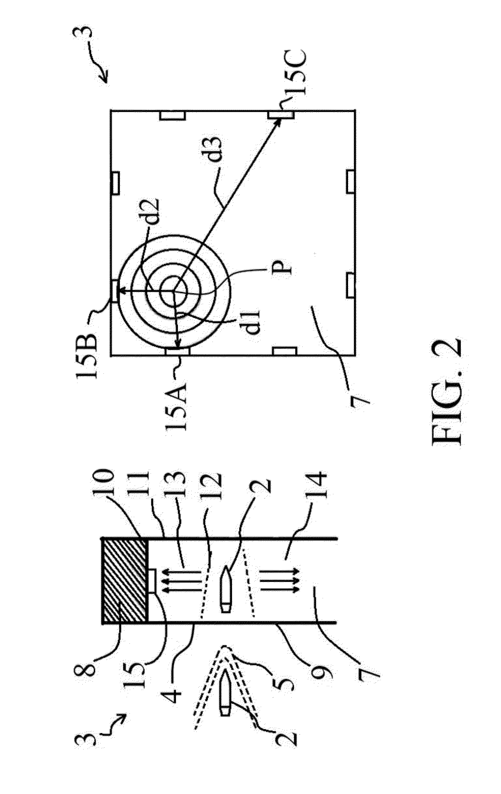
[0028]using redundant information provided by all combinations of 3-sensors to correct each sensor error and to increase further accuracy by applying a statistical calculation in real-time for every shot.
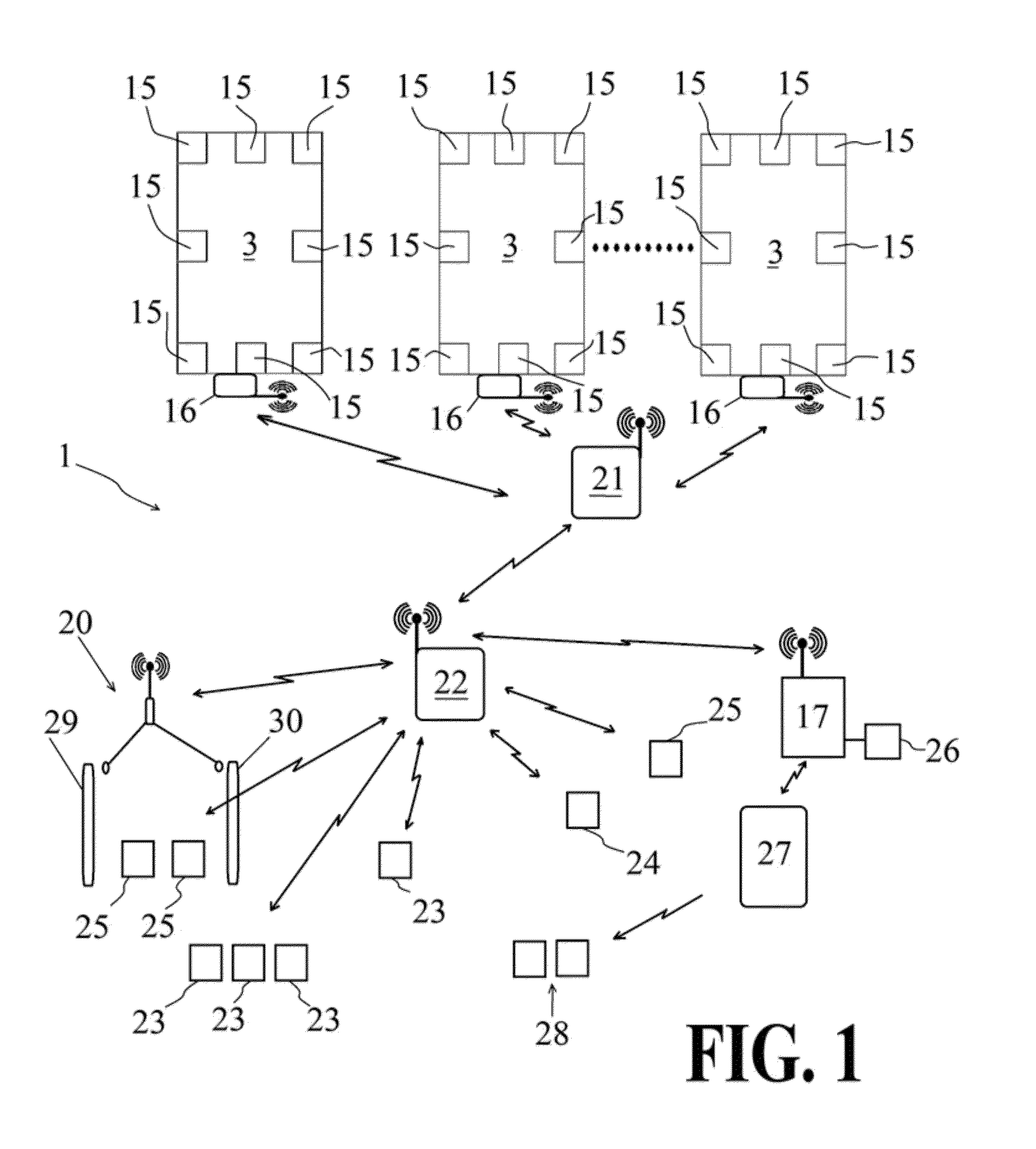
[0029]It can therefore be seen that there is advantageously provided a target that can use five or more pressure sensors to more accurately determine the location of impact of a projectile on the target. Further, additional sensors can be used as desired without significantly increasing the computational load on the target controller. The use of the five or more sensors not only provides more accurate determination of projectile position but also allows the provision of redundant information to ignore spurious or inaccurate data and increase reliability.
[0030]Yet further, the simple wireless set up between target,

Problems solved by technology

Various electronic target devices have been developed, and it will be appreciated that a distinct problem of providing a projectile target is that the target gets shot, thereby damaging it.
An array of sensors disposed over the face of the target would each be damaged or destroyed by a projectile passing through it and so a simple two-dimensional detector on or over the target face is of little practical value.
These prior art targets are sufficient for providing a rough estimation of the location the projectile hits the face of the target, however, they are not reliable.
For example, the prior art targets are prone to designate a miss when

Method used


Image

  • Projectile target system
  • Projectile target system
  • Projectile target system

Examples


Embodiment Construction

[0042]The ensuing detailed description provides preferred exemplary embodiments only, and is not intended to limit the scope, applicability, or configuration of the invention. Rather, the ensuing detailed description of the preferred exemplary embodiments will provide those skilled in the art with an enabling description for implementing the preferred exemplary embodiments of the invention. It being understood that various changes may be made in the function and arrangement of elements without departing from the spirit and scope of the invention, as set forth in the appended claims.

[0043]To aid in describing the invention, directional terms are used in the specification and claims to describe portions of the present invention (e.g., upper, lower, left, right, etc.). These directional definitions are merely intended to assist in describing and claiming the invention and are not intended to limit the invention in any way. In addition, reference numerals that are introduced in the spec...


PUM


Abstract

According to one aspect of the present invention, a projectile target is disclosed comprising a target having a substantially sealed chamber having a front face and a rear face with an enclosing side wall disposed intermediate. The front and rear faces are formed by membranes configured to allow a projectile to pass therethrough and then substantially seal to maintain the substantially sealed chamber. Pressure wave sensors are disposed within the chamber and are configured to detect pressure waves created by the projectile. A target controller receives signals from the pressure sensors indicative of the pressure sensed by the sensors and determines an impact point of the projectile on the front face of the target.

Description

CROSS REFERENCE TO RELATED APPLICATIONS[0001]This application claims priority from Australian Patent Application Serial No. 2011250746, filed on 13 Nov. 2011.BACKGROUND OF THE INVENTION[0002]The present invention relates to projectile targets and, in particular, to an electronic projectile target.[0003]The invention has been developed primarily for use as firearm projectile range targets and will be described hereinafter with reference to this application. However, it will be appreciated that the invention is not limited to this particular field of use and is applicable to other projectiles, for example, arrows.[0004]It is now becoming known to use electronic targets in shooting ranges. The use of electronic target allows a shooter to fire projectiles at target and not have to physically retrieve the target or observe this through the use of binoculars or a rangefinder in order to determine the location a projectile hits the target.[0005]It is crucially important in competitive shoo...

Claims


Application Information

Patent Timeline
IPC IPC(8): F41J5/06F41J5/14
CPCF41J5/06F41J5/056F41J5/14
Inventor KAZAKOV, DMITRIGERASIMOV, VADIM
Owner HEX SYST
Why Eureka
Try Eureka