
Wireless communication system, and small portable device, housing case for a small portable device, and communication device for a small portable device to be used in the wireless communication system

a communication device and wireless communication technology, which is applied in the direction of antennas, antenna details, electrical devices, etc., can solve the problems of reducing the thickness and size of the small portable device, and severely restricting the size of the second coil that can be mounted therein, so as to suppress the reduction of receiving sensitivity

Inactive Publication Date: 2013-08-01
SUMIDA CORP
View PDF5 Cites 11 Cited by
  • Summary
  • Abstract
  • Description
  • Claims
  • Application Information

AI Technical Summary

Benefits of technology

The present invention provides a wireless communication system that can suppress a reduction in receiving sensitivity even when the second coil is reduced in size. Additionally, the invention provides small portable devices, a housing case for a small portable device, and a communication device for a small portable device that can be used in this wireless communication system. This means that the wireless communication system can effectively reduce the size of the second coil without compromising its performance.

Problems solved by technology

In a device of relatively small size, in particular, a small portable device such as a mobile telephone or an IC card, the size and volume of the device itself are small, and hence the size of the second coil that can be mounted therein is also restricted severely.
However, when the second coil is increased in size, reductions in thickness and size of the small portable device are hindered.

Method used


Image

  • Wireless communication system, and small portable device, housing case for a small portable device, and communication device for a small portable device to be used in the wireless communication system
  • Wireless communication system, and small portable device, housing case for a small portable device, and communication device for a small portable device to be used in the wireless communication system
  • Wireless communication system, and small portable device, housing case for a small portable device, and communication device for a small portable device to be used in the wireless communication system

Examples


Embodiment Construction

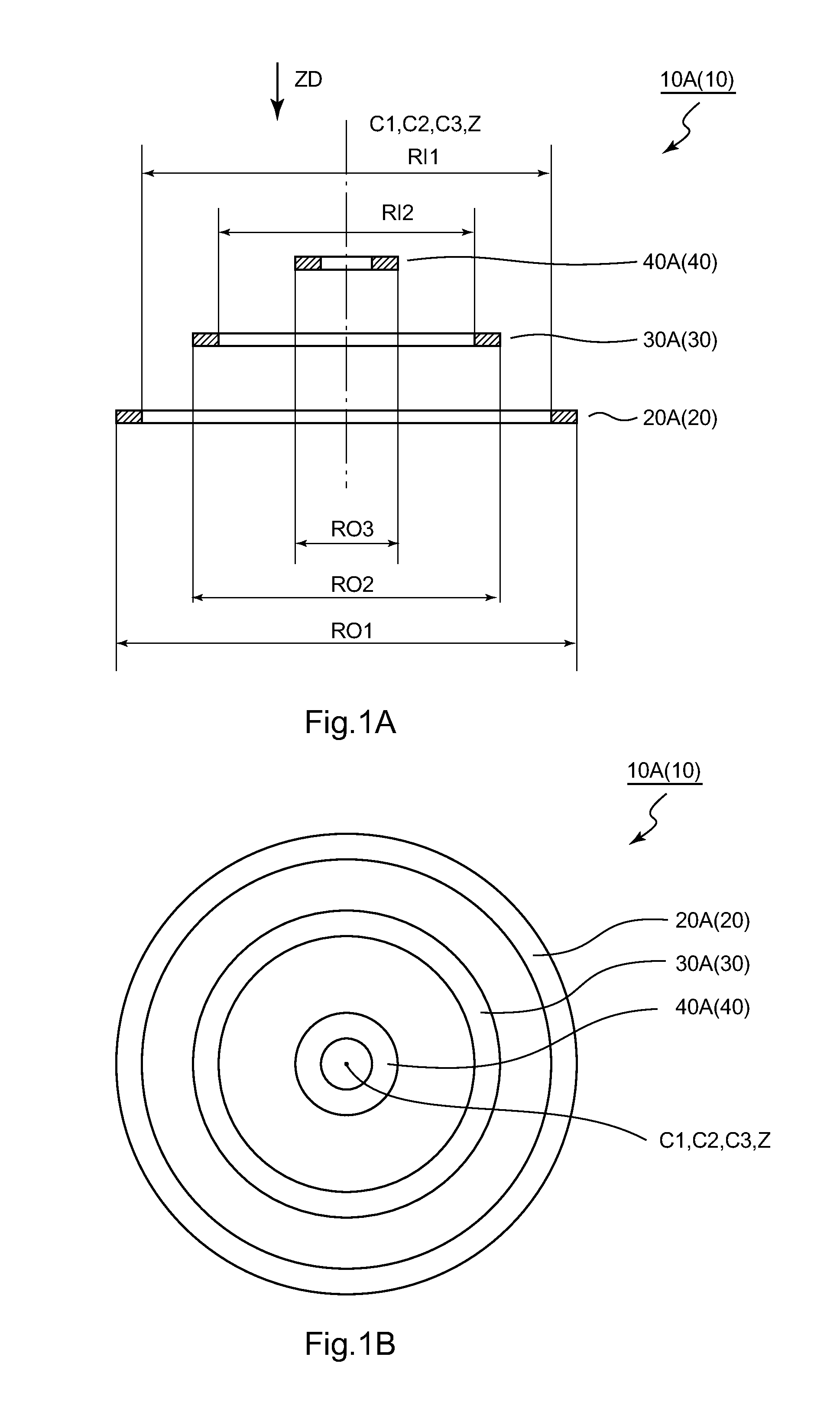
[0039]FIGS. 1A and 1B are schematic views illustrating an example of a wireless communication system according to an embodiment. Of the figures, FIG. 1A is a schematic cross-sectional view illustrating a state in which three kinds of coils 20A (20), 30A (30), and 40A (40) constituting a wireless communication system 10A (10) are cut by a plane including center axes C1, C2, and C3 of the respective coils 20, 30, and 40, and FIG. 1B is a schematic plan view illustrating the three kinds of coils 20A, 30A, and 40A constituting the wireless communication system 10A when viewed in a direction of the arrow ZD of FIG. 1A. In FIGS. 1A and 1B, illustration of components constituting the wireless communication system 10A other than the coils 20A, 30A, and 40A, and of lead wires and the like constituting the coils 20A, 30A, and 40A is omitted.

[0040]As illustrated in FIGS. 1A and 1B, the wireless communication system 10 according to the embodiment includes a first coil 20 having at least a funct...


PUM


Abstract

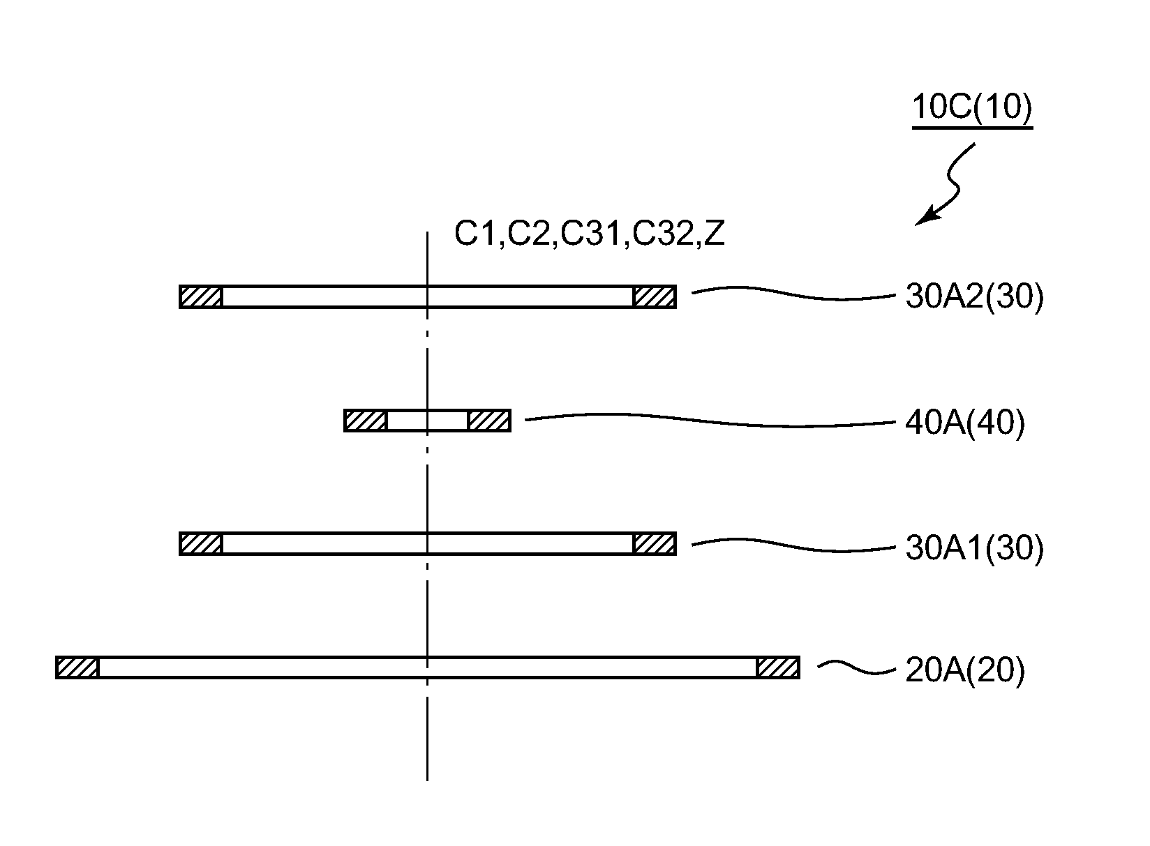
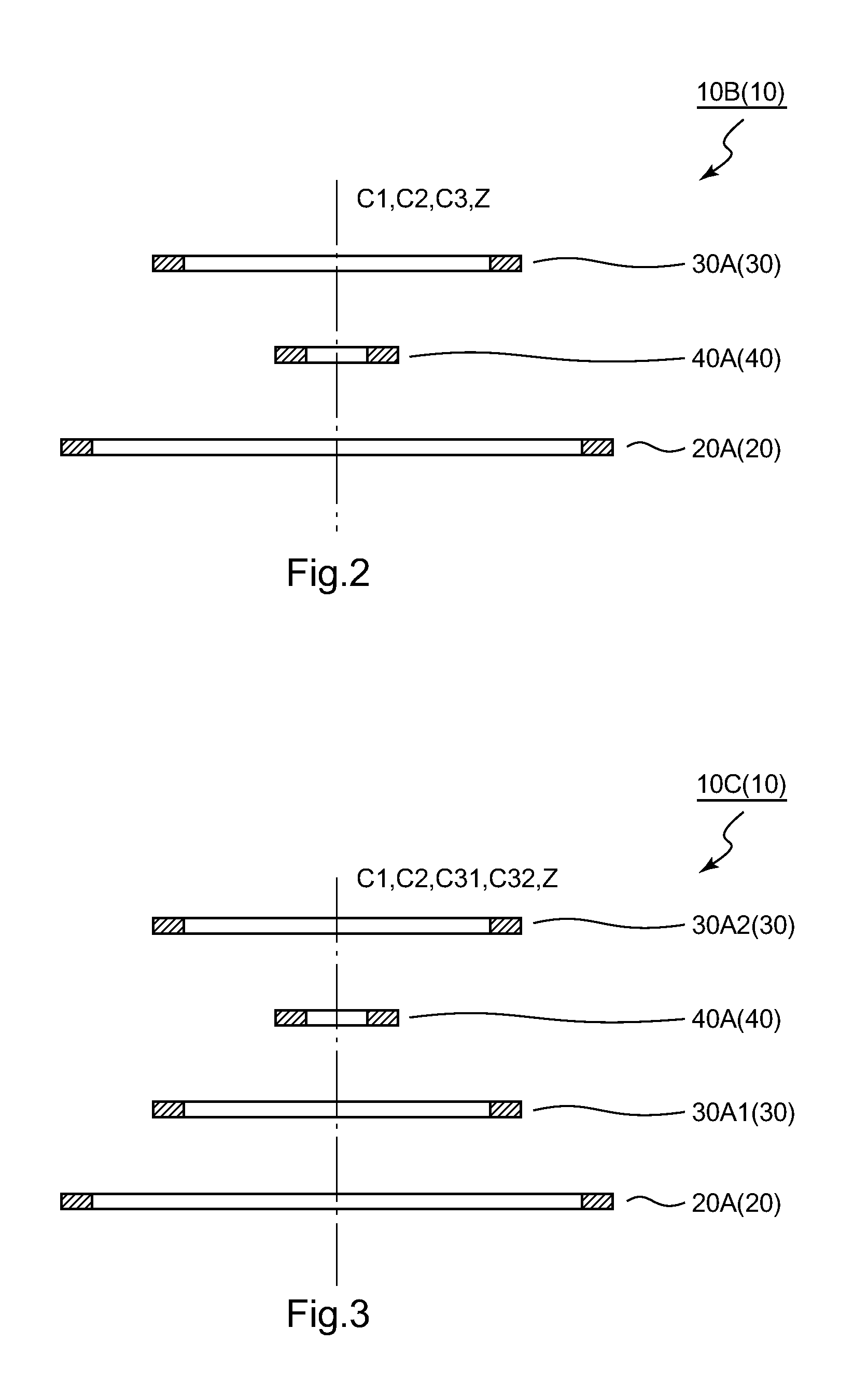
A wireless communication system may include a first coil having at least a function of transmitting signal information, a relay coil, and a second coil having at least a function of receiving the signal information, and satisfying Equation (1): RO1>RO2>RO3, where RO1 represents an outer diameter of the first coil, RO2 represents an outer diameter of the relay coil, and RO3 represents an outer diameter of the second coil, and a small portable device, a housing case for a small portable device, and a communication device for a small portable device to be used in the wireless communication system.

Description

CROSS-REFERENCE TO RELATED APPLICATIONS[0001]The present application claims priority from Japanese Patent Application No. 2012-020152 filed on Feb. 1, 2012 and Japanese Patent Application No. 2012-182966 filed on Aug. 22, 2012, the entirety of both applications is hereby incorporated by reference into this application.BACKGROUND[0002]1. Field of the Invention[0003]At least an embodiment of the present invention may relate to a wireless communication system, and a small portable device, a housing case for a small portable device, and a communication device for a small portable device to be used in the wireless communication system.[0004]2. Description of the Related Art[0005]In near field communication (NFC) for a communication range of about several to a dozen centimeters, data communication can be performed easily when one piece of equipment is brought close to or in contact with the other piece of equipment. In such wireless communication, a magnetic flux generated by a first coil...

Claims


Application Information

Patent Timeline
Patent Type & Authority Applications(United States)
IPC IPC(8): H01Q7/00
CPCH01Q1/2208H01Q7/00
Inventor KURODA, MORIHIROKIKUCHI, SHUICHI
Owner SUMIDA CORP
Learn More