Image Forming Device

Inactive Publication Date: 2013-08-01
MURATA MASCH LTD
View PDF4 Cites 21 Cited by
  • Summary
  • Abstract
  • Description
  • Claims
  • Application Information

AI Technical Summary

Benefits of technology

[0007]An object of the present invention is to provide an image forming device capable of simplifying a head moving struct

Problems solved by technology

However, the operation projection, the operation arm, the wire, the guide pulley, and the like are required to be arranged between the operation lever and the front d

Method used


Image

  • Image Forming Device
  • Image Forming Device
  • Image Forming Device

Examples


Embodiment Construction

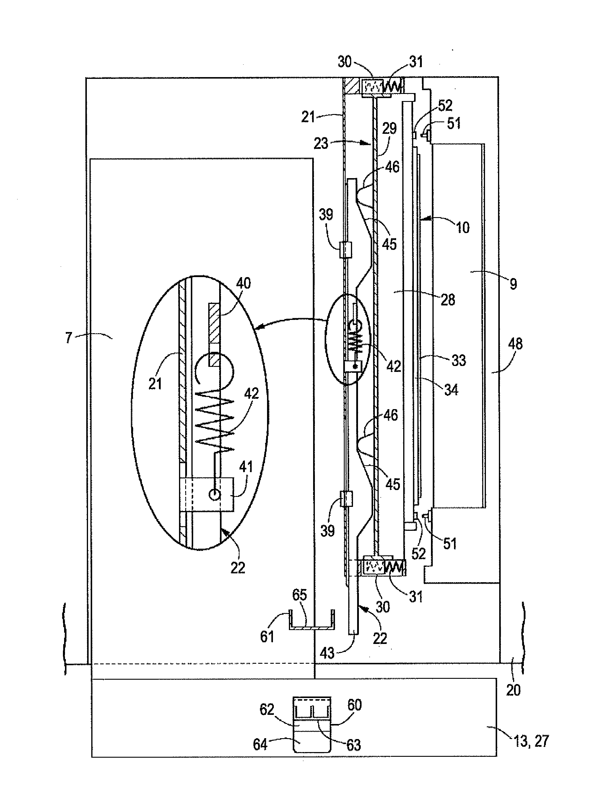
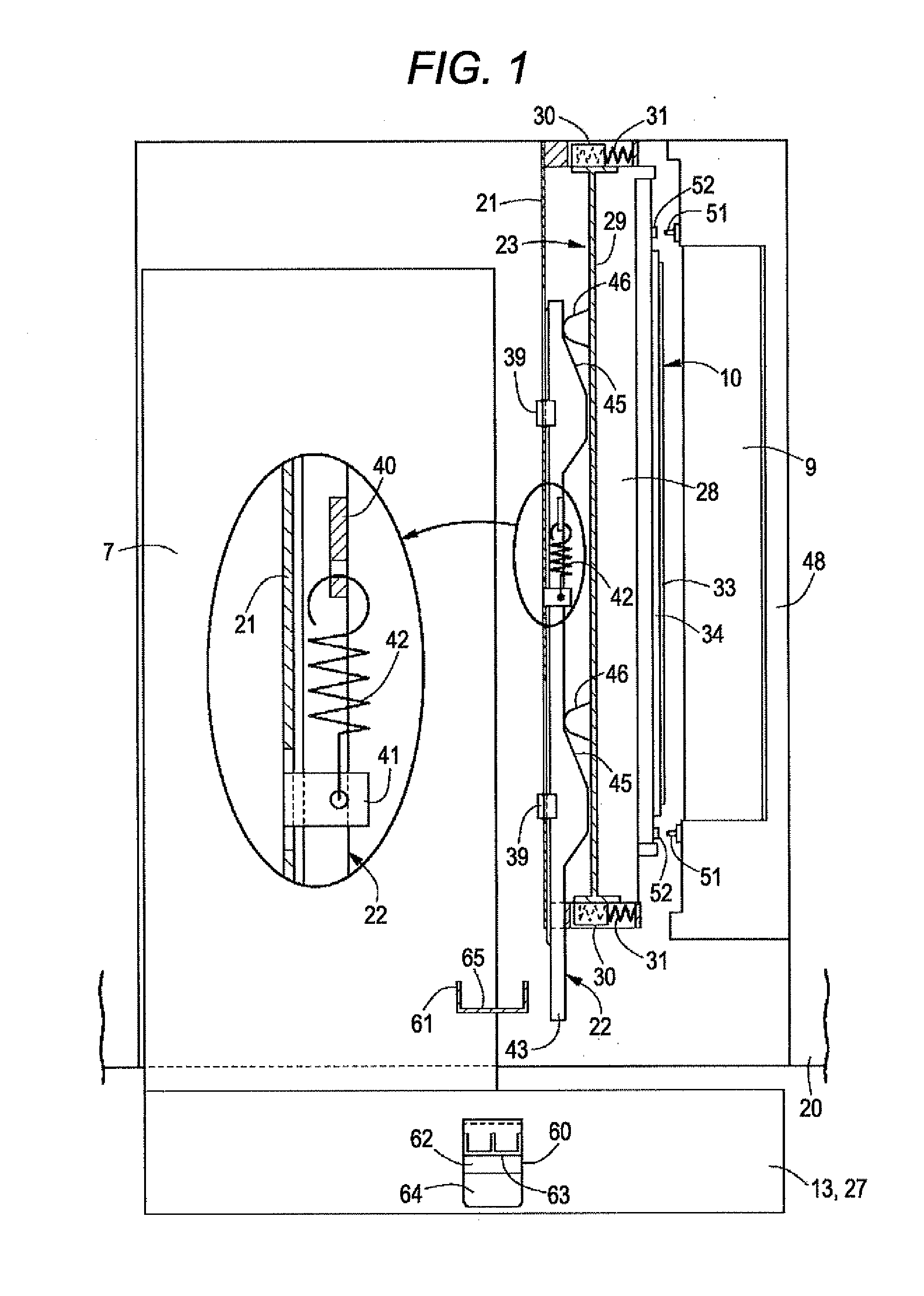
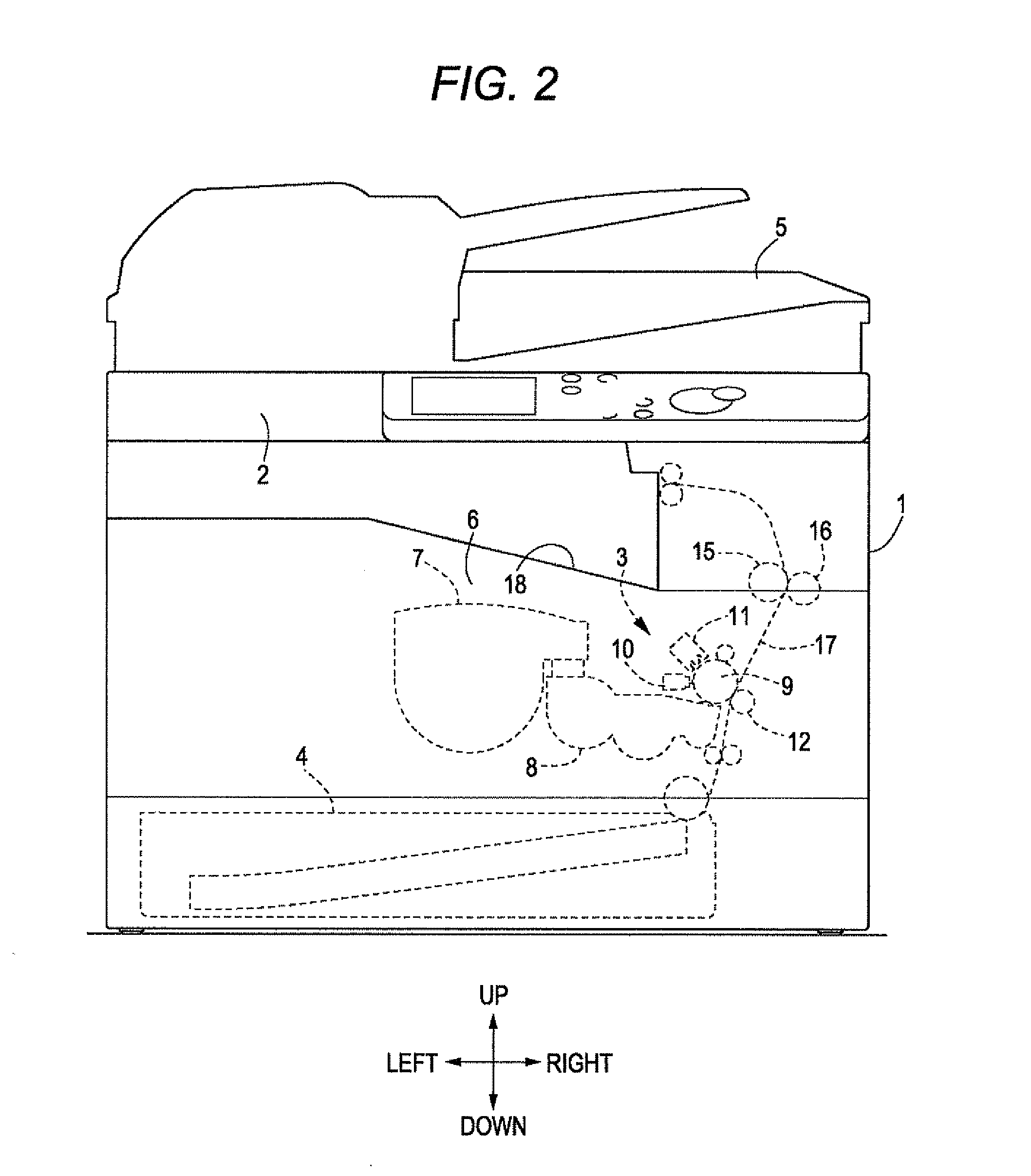
[0039]FIGS. 1-9 illustrate an embodiment in which a head moving structure of an image forming device according to the present invention is applied to a multifunction peripheral having a copy function and a facsimile function. Front and back, left and right, and up and down directions in the present invention are as indicated with cross arrows in FIGS. 2 and 4. The front and back direction and the left and right direction are directions in a horizontal plane, and the up and down direction is defined as a vertical direction. The front and back direction is parallel to a rotation axis (a first axis line 22A, or sliding direction of a slide frame 22) of a photosensitive drum 9, and the left and right direction is parallel to a second axis line 23A (sliding direction of a head supporting frame 23).

[0040]The multifunction peripheral in FIG. 2 includes an image scanning unit 2 arranged on an upper side of a main body 1, an image forming unit 3 arranged closer to one side of the main body 1...


PUM


Abstract

An image forming device includes a fixed frame, a slide frame, a head supporting frame, a cam structure, and an operation body. The fixed frame is arranged adjacent to a photosensitive body. The slide frame is supported in a slidable manner along a first axis line by the fixed frame. The head supporting frame is supported in a slidable manner along a second axis line, which intersects the first axis line, by the fixed frame, and supports an exposure head. The cam structure converts an operation in which the slide frame slides to an operation in which the head supporting frame slides. The operation body moves the exposure head between a separated position and a proximate position by sliding the slide frame.

Description

CROSS-REFERENCE TO RELATED APPLICATIONS[0001]This application claims priority under 35 U.S.C. 119 to Japanese Patent Application No. 2012-015004, filed on Jan. 27, 2012, which application is hereby incorporated by reference in its entirety.BACKGROUND OF THE INVENTION[0002]1. Field of the Invention[0003]The present invention relates to an image forming device including an exposure head for forming a latent image on a photosensitive body (photosensitive drum or photosensitive belt).[0004]2. Description of Related Art[0005]Conventionally, there is known an image forming device in which the exposure head is moved to a proximate position from a separated position with respect to a photosensitive drum using an opening / closing operation of a front door. The exposure head is supported with a frame body so as to be brought into proximity to or separated from the photosensitive drum, and is biased towards the separated position with a spring. The frame body includes an operation lever for mov...

Claims


Application Information

Patent Timeline
IPC IPC(8): B41J2/385
CPCG03G15/04045G03G15/04G03G21/1666G03G21/1633B41J25/308B41J2/45B41J2/47
Inventor SHIMAMOTO, HIDEATSU
Owner MURATA MASCH LTD
Why Eureka
Try Eureka