Protective Telecommunications Enclosure Systems and Methods

a technology for enclosures and telecommunications equipment, applied in the direction of supporting structures, manufacturing tools, standard structures, etc., can solve the problems of high cost and unsuitable for efficient use with standard sized telecommunication storage facilities and components, and achieve the effect of efficient and effective us

Active Publication Date: 2013-08-01
CENTURYLINK INTPROP
View PDF9 Cites 37 Cited by
  • Summary
  • Abstract
  • Description
  • Claims
  • Application Information

AI Technical Summary

Benefits of technology

[0009]A telecommunications enclosure encompasses a case or a housing with an interior rack that is dedicated to the telecommunications function and related support facilities. For example, an enclosure can include an integrated telecommunications cabinet and rack. Advantageously, enclosure embodiments of the present invention can be used efficiently and effectively in any of a variety of telecommunications room or space configurations. These enclosures include electrical and fiber entrances which are placed to accommodate a telecommunications environment.
[0010]In a first aspect, embodiments of the present invention provide a method of producing a HEMP protected enclosure for holding an electronic device. The method may include, for example, building a test HEMP protected enclosure according to an enclosure design, performing an acceptance testing procedure on the test HEMP protected enclosure, determining whether the test HEMP protected enclosure meets a HEMP protection level according to MIL STD 188 125 1, and producing a plurality of HEMP protected enclosures according to the enclosure design if the test HEMP protected enclosure meets the HEMP protection level according to MIL STD 188 125 1. In some cases, the test HEMP protected enclosure has a maximum cabinet width dimension that does not exceed about 26 inches and a maximum cabinet depth dimension that does not exceed about 22⅜ inches. In some cases, the test HEMP protected enclosure has a maximum cabinet height dimension that does not exceed about 84 inches. The test HEMP protected enclosure can have a power input point of entry that facilitates entry of a power cable to the interior space from a location external to the cabinet, and a fiber optic cable point of entry that facilitates entry of a fiber optic cable to the interior space from a location external to the cabinet.
[0014]In a further aspect, embodiments of the present invention encompass methods of producing a HEMP protected enclosure for holding an electronic device that include building a test HEMP protected enclosure according to an enclosure design, performing an acceptance testing procedure on the test HEMP protected enclosure, determining whether the test HEMP protected enclosure meets a HEMP protection level according to MIL STD 188 125 1, and producing a plurality of HEMP protected enclosures according to the enclosure design if the test HEMP protected enclosure meets the HEMP protection level according to MIL STD 188 125 1, where the test HEMP protected enclosure includes a cabinet width dimension of about 26 inches and a cabinet depth dimension of about 38 inches, a cabinet width dimension of about 65 inches and a cabinet depth dimension of about 30 inches, or a cabinet width dimension of about 26 inches and a cabinet depth dimension of about 20¼ inches. In some cases, the test HEMP protected enclosure includes a cabinet width dimension of about 26 inches and a cabinet depth dimension of about 38 inches. In some cases, the test HEMP protected enclosure includes a cabinet width dimension of about 65 inches and a cabinet depth dimension of about 30 inches. In some cases, the test HEMP protected enclosure includes a cabinet width dimension of about 26 inches and a cabinet depth dimension of about 20¼ inches. In some cases, the test HEMP protected enclosure includes a maximum cabinet height dimension that does not exceed about 84 inches. Optionally, the test HEMP protected enclosure may include a power input point of entry that facilitates entry of a power cable to the interior space from a location external to the cabinet, and a fiber optic cable point of entry that facilitates entry of a fiber optic cable to the interior space from a location external to the cabinet.
[0017]In another aspect, embodiments of the present invention provide a method of producing a HEMP protected enclosure for holding an electronic device. The method may include, for example, building a test HEMP protected enclosure according to an enclosure design, performing an acceptance testing procedure on the test HEMP protected enclosure, determining whether the test HEMP protected enclosure meets a HEMP protection level according to MIL-STD-188-125-1, and producing a plurality of HEMP protected enclosures according to the enclosure design if the test HEMP protected enclosure meets the HEMP protection level according to MIL-STD-188-125-1. In some cases, the test HEMP protected enclosure has a maximum cabinet width dimension that does not exceed about 90 inches and a maximum cabinet depth dimension that does not exceed about 30 inches. In some cases, the test HEMP protected enclosure has a maximum cabinet height dimension that does not exceed about 94 inches. The test HEMP protected enclosure can have a power input point of entry that facilitates entry of a power cable to the interior space from a location external to the cabinet, and a fiber optic cable point of entry that facilitates entry of a fiber optic cable to the interior space from a location external to the cabinet.
[0019]In some cases, the enclosure provides a HEMP protection level to the telecommunications device of at least 100 dB attenuation at 1 GHz. In related cases, the enclosure provides a HEMP protection level to the telecommunications device of at least 80 dB attenuation at 1 GHz. The enclosure can further include a power input point of entry that facilitates entry of a power cable to the interior space from a location external to the cabinet, and a fiber optic cable point of entry that facilitates entry of a fiber optic cable to the interior space from a location external to the cabinet. Similarly, the enclosure may include a converter, and a battery coupled with the converter. The enclosure can also include a power filter. A clean output of the power filter can be disposed within the interior space of the cabinet. A dirty input of the power filter can be disposed external to the cabinet. In some cases, the cabinet includes a front opening that is configured to receive the electronic device therethrough. A front opening of the cabinet can have a width dimension of about 23.5 inches. In some aspects, the enclosure includes a power input point of entry that facilitates entry of a power cable to the interior space from a location external to the cabinet, where the power input point of entry is disposed at a top surface of the enclosure. In some aspects, the enclosure includes a fiber optic cable point of entry that facilitates entry of a fiber optic cable to the interior space from a location external to the cabinet, where the fiber optic cable point of entry is disposed at a top surface of the enclosure. The enclosure may also include a power cable coupled with the power input point of entry, and a fiber optic cable coupled with the fiber optic cable point of entry.

Problems solved by technology

Current approaches for protecting telecommunications racks and enclosures from HEMP exposure are often costly, however, and not well suited for efficient use with standard sized telecommunications storage facilities and components.

Method used


Image

  • Protective Telecommunications Enclosure Systems and Methods
  • Protective Telecommunications Enclosure Systems and Methods
  • Protective Telecommunications Enclosure Systems and Methods

Examples


Embodiment Construction

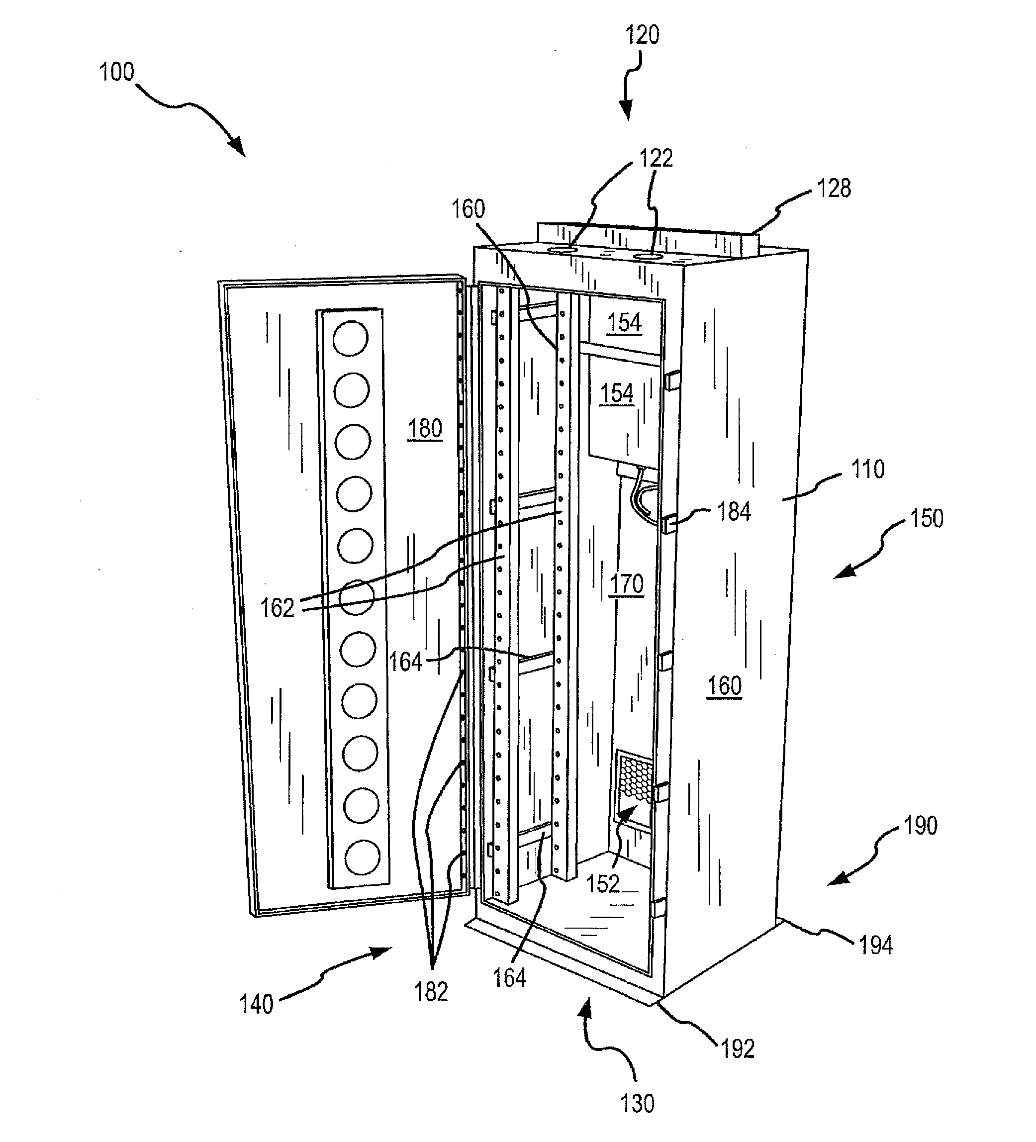
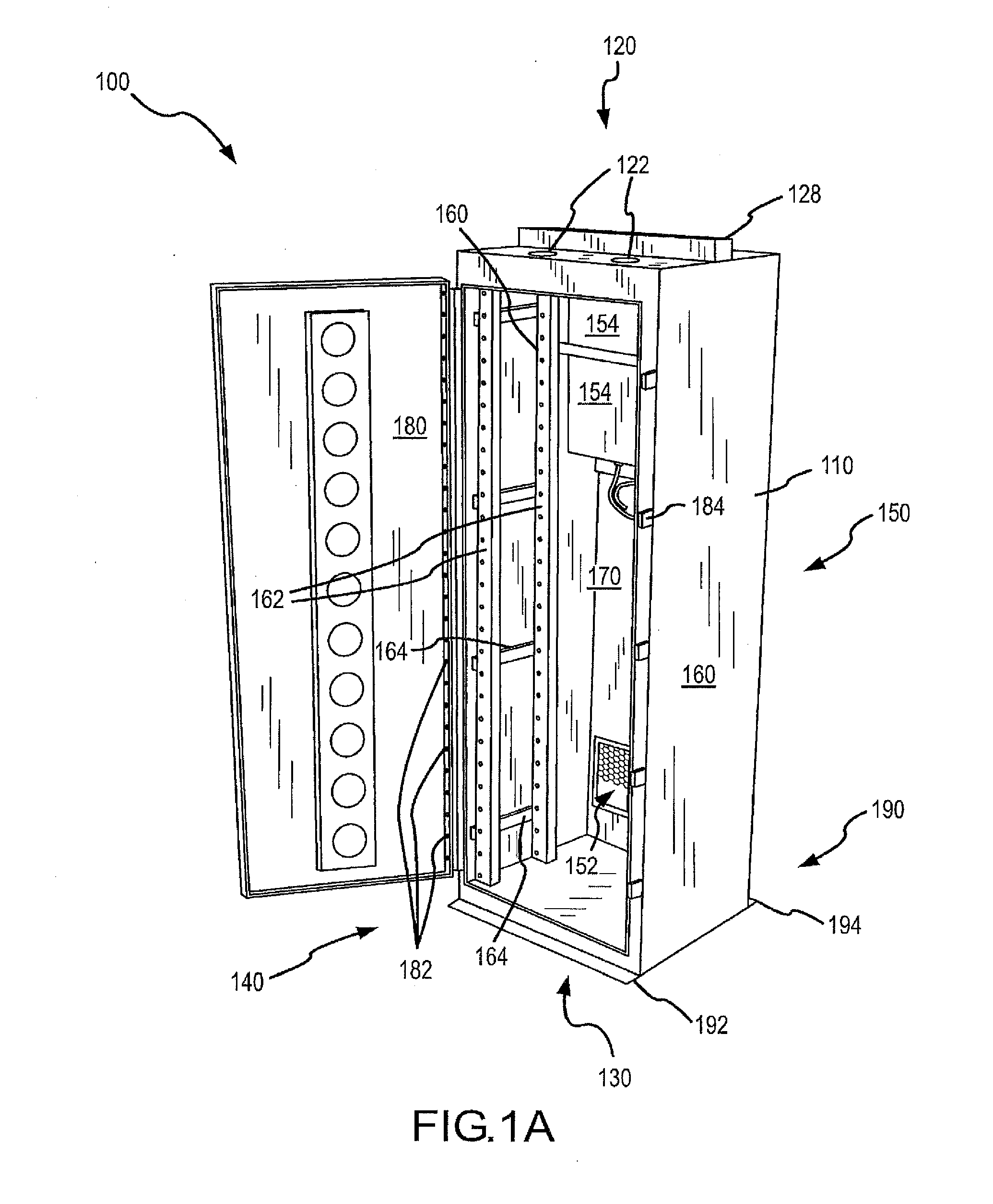
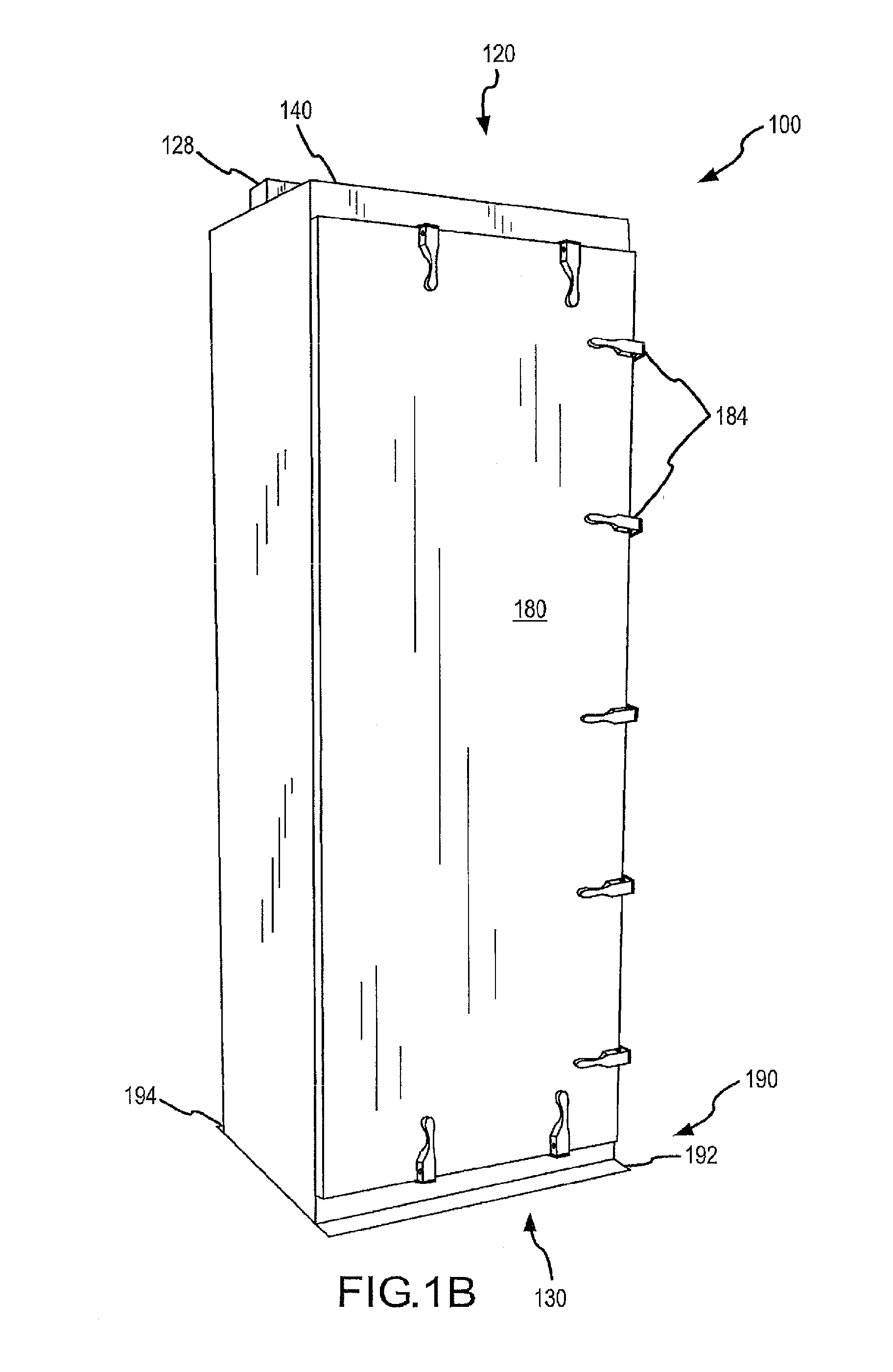
[0059]While various aspects and features of certain embodiments have been summarized above, the following detailed description illustrates a few exemplary embodiments in further detail to enable one of skill in the art to practice such embodiments. The described examples are provided for illustrative purposes and are not intended to limit the scope of the invention.

[0060]In the following description, for the purposes of explanation, numerous specific details are set forth in order to provide a thorough understanding of the described embodiments. It will be apparent to one skilled in the art, however, that other embodiments of the present invention may be practiced without some of these specific details. In other instances, certain structures and devices are shown in block diagram form. Several embodiments are described herein, and while various features are ascribed to different embodiments, it should be appreciated that the features described with respect to one embodiment may be i...


PUM

PropertyMeasurementUnit
widthaaaaaaaaaa
heightaaaaaaaaaa
depthaaaaaaaaaa

Abstract

Protective containers for electronic equipment, and methods of testing, use, and / or manufacture thereof, are provided. The cabinets provide a HEMP protection level to electronic equipment housed therein that meets a HEMP protection level according to MIL-STD-188-125-1.

Description

CROSS-REFERENCES TO RELATED APPLICATIONS[0001]This application claims priority to U.S. Patent Application Ser. No. 61 / 716,385 (the “'385 application”), filed Oct. 19, 2012 by Hector Rojo et al. (attorney docket no. 020370-007800US), entitled, “Protective Telecommunications Enclosure Systems and Methods.”[0002]This application is also a continuation-in-part of U.S. patent application Ser. No. 13 / 616,249, filed Sep. 14, 2012 by Heimann et al. (attorney docket no. 020370-007100US), which is a divisional of U.S. patent application Ser. No. 12 / 714,337, (now U.S. Pat. No. 8,289,717), filed Feb. 26, 2010 by Heimann et al. (attorney docket no. 020366-099810US), which is a continuation-in-part of, U.S. patent application Ser. No. 11 / 780,045 filed Jul. 19, 2007 by Heimann et al. (attorney docket no. 020366-099800US).[0003]The entire disclosure of each of these applications is incorporated herein by reference in their entirety for all purposes.COPYRIGHT STATEMENT[0004]A portion of the disclosu...

Claims


Application Information

Patent Timeline
Patent Type & Authority Applications(United States)
IPC IPC(8): H05K9/00H05K13/00
CPCH04Q1/112H04Q1/116H04Q1/025H04Q1/066H04Q1/10Y10T29/49764H05K9/0062H04Q1/03H05K9/0007H05K13/0023Y10T29/49826H05K7/1495Y10T29/49004Y10T29/49771H05K13/00
Inventor ROJO, HECTORKINLEY, RAYMOND LEESATTLER, STEPHEN
Owner CENTURYLINK INTPROP
Why Eureka
Try Eureka