Ophthalmic apparatus, control method of ophthalmic apparatus and storage medium

Active Publication Date: 2013-08-01
CANON KK
View PDF4 Cites 9 Cited by
  • Summary
  • Abstract
  • Description
  • Claims
  • Application Information

AI Technical Summary

Benefits of technology

The invention is a system and method for displaying a specific region of interest on a fundus image, which is useful for identifying and measuring features of the eye. The system includes an imaging unit that captures fundus images, a calculation unit that calculates the displacement of the imaging position between images, and a display control unit that locates the region of interest on the fundus image based on the calculated displacement. The technical effect of this invention is improved visualization of the fundus image, allowing for easier identification and measurement of specific features.

Problems solved by technology

According to Japanese Patent Laid-Open No. 2010-227610, however, although this technique sets control parameters for a scanner which operates OCT measurement light based on the position designated on a still fundus image, it gives no consideration to the influence of fine fixation movement.
When capturing an OCT image while tracking the fundus as in Japanese Patent No. 4262603, this technique faces the problem that the position of a region of interest designated on a fundus image may differ from the actual imaging position of a tomographic image.

Method used


Image

  • Ophthalmic apparatus, control method of ophthalmic apparatus and storage medium
  • Ophthalmic apparatus, control method of ophthalmic apparatus and storage medium
  • Ophthalmic apparatus, control method of ophthalmic apparatus and storage medium

Examples


first embodiment

[0021]This embodiment will exemplify a case in which when capturing a tomographic image of the fundus while tracking the fundus, the apparatus displays a fundus image and a region of interest indicating the position of a tomographic image so as to locate the region of interest at a predetermined position on the fundus image.

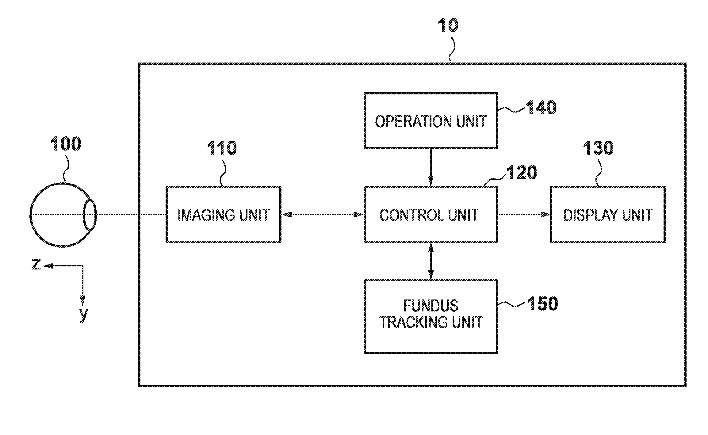
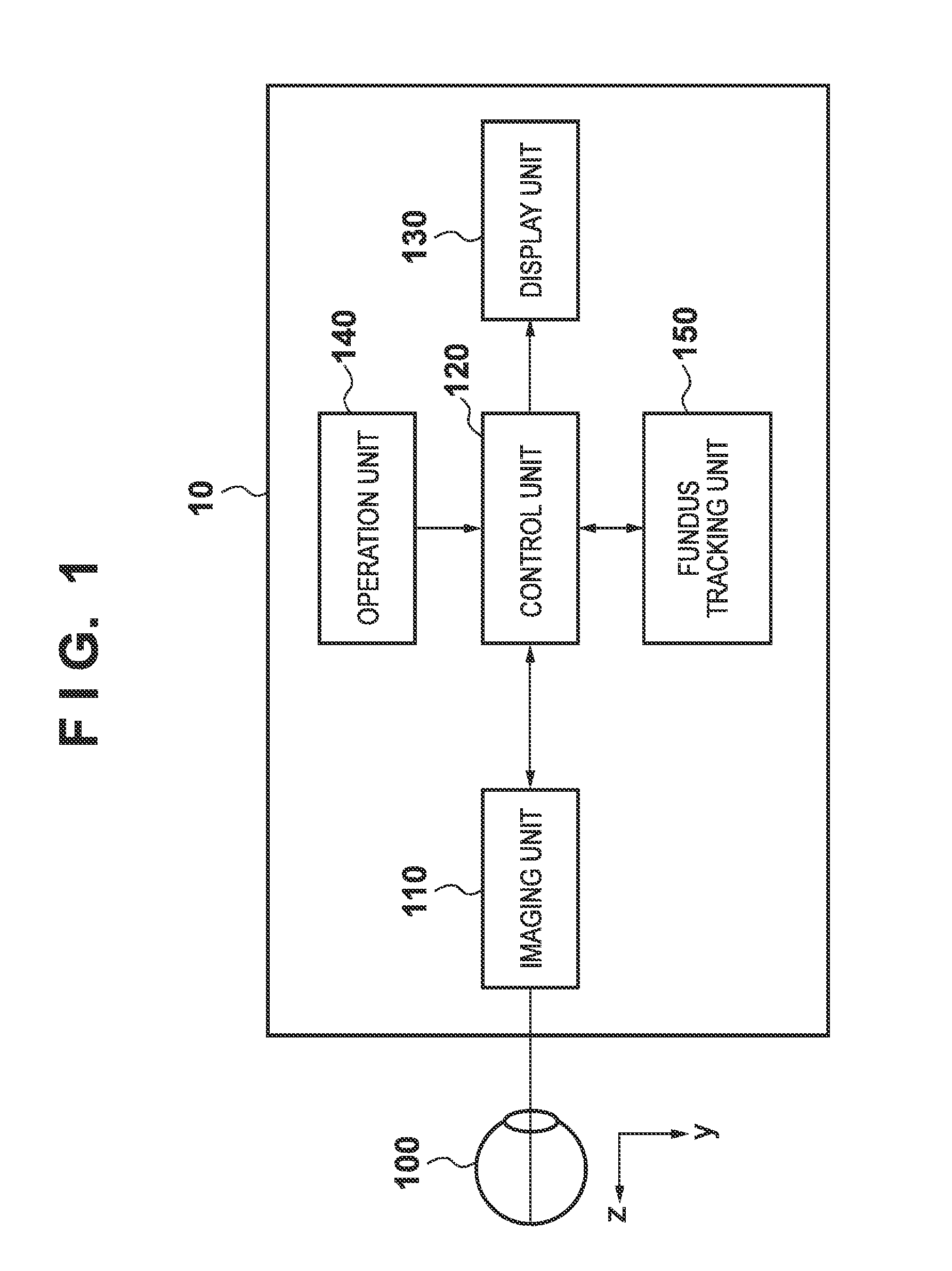
[0022]An example of the arrangement of an ophthalmic apparatus 10 according to the first embodiment will be described first with reference to FIG. 1. The ophthalmic apparatus 10 includes an imaging unit 110, a control unit 120, a display unit 130, an operation unit 140, and a fundus tracking unit 150. The functions of the respective processing units will be sequentially described below.

[0023]110>

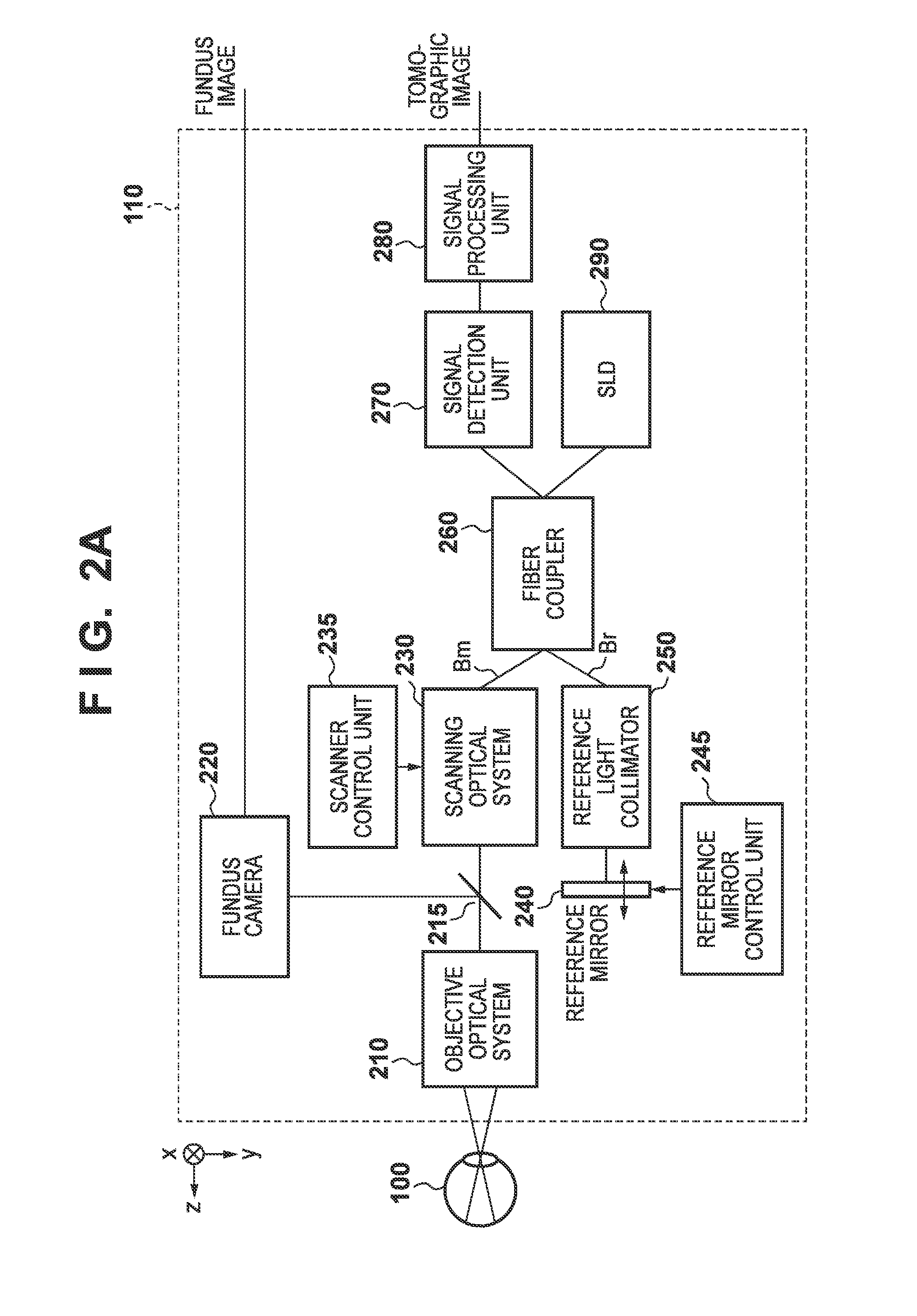
[0024]The imaging unit 110 functions as a fundus imaging unit which captures a two-dimensional image (fundus image) of the fundus of an eye 100 to be examined or a tomographic unit which captures a tomographic image of the eye 100. An example of the arrangement of the ima...

second embodiment

[0054]The first embodiment has exemplified the case in which the apparatus corrects the display position of a region of interest (a region indicating the imaging region and imaging position of a tomographic image) based on the tracking information (displacement amount) between fundus images, moves the region of interest, and superimposes / displays it on the fundus image, thereby allowing accurate comprehension of the imaging position of a tomographic image. In contrast to this, the second embodiment will exemplify a method of controlling the display position of a fundus image based on the tracking information of the fundus image.

[0055]The arrangement of an ophthalmic apparatus 10 according to the second embodiment is the same as that described in the first embodiment, and hence a description of it will be omitted. In addition, a procedure for processing according to the second embodiment is the same as that indicated by the flowchart of FIG. 3 in the first embodiment except for step ...

third embodiment

[0064]The first embodiment has exemplified the case in which the apparatus superimposes and displays a region of interest on a fundus image based on the tracking information of the fundus image to allow accurate comprehension of the imaging position of a tomographic image. In contrast to this, the third embodiment will exemplify a display control method of reducing the movement of a region of interest when the operator operates the region of interest. The arrangement of an ophthalmic apparatus 10 according to the third embodiment is the same as that described in the first embodiment, and hence a description of it will be omitted.

[0065]A concrete procedure for the processing executed by the ophthalmic apparatus 10 according to the third embodiment will be described with reference to the flowchart of FIG. 7. Note however that the processing in each of steps S710, S720, and S740 is the same as that in each of steps S310, S320, and S340, and hence a description of it will be omitted.

[00...


PUM


Abstract

An ophthalmic apparatus comprises an imaging unit which images a fundus of an eye to be examined; a calculation unit which calculates a displacement of an imaging position of the imaging unit between fundus images captured by the imaging unit; and a display control unit which causes a display unit to display a fundus image captured by the imaging unit and a region of interest so as to locate the region of interest at a predetermined position on the fundus image based on the displacement calculated by the calculation unit.

Description

BACKGROUND OF THE INVENTION[0001]1. Field of the Invention[0002]The present invention relates to an ophthalmic apparatus, a control method of the ophthalmic apparatus, and a storage medium.[0003]2. Description of the Related Art[0004]An ophthalmic tomographic apparatus such as an OCT (Optical Coherence Tomography) allows three-dimensional observation of the internal state of the retinal layer. This apparatus is effective in diagnosing diseases more accurately, and hence has recently attracted much attention.[0005]Japanese Patent Laid-Open No. 2010-227610 discloses a technique of setting imaging parameters for OCT images based on the measurement position designated on a fundus image of the eye to be examined. Japanese Patent No. 4262603 discloses a technique of correcting an OCT imaging position while tracking the fundus to capture OCT images at the same position on the retina because of the fine fixation movement of the eye to be examined.[0006]According to Japanese Patent Laid-Open...

Claims


Application Information

Patent Timeline
IPC IPC(8): G06K9/00
CPCA61B3/12A61B3/102
Inventor SAKAGAWA, YUKIO
Owner CANON KK
Why Eureka
Try Eureka