Apparatus and Method for a Dynamic "Region of Interest" in a Display System

a dynamic and display system technology, applied in the field of displays, can solve the problems of latency, degradation, and image presented to the wearer that has a significant level of magnification, and achieve the effect of improving the usability of an imag

Active Publication Date: 2011-02-24
ESIGHT CORP
View PDF60 Cites 274 Cited by
  • Summary
  • Abstract
  • Description
  • Claims
  • Application Information

AI Technical Summary

Benefits of technology

[0030]FIGS. 9a through 9c depict the results of an image enhancement algorithm th

Problems solved by technology

This can result in an image presented to the wearer that has a significant level of magnification, with nei

Method used


Image

  • Apparatus and Method for a Dynamic "Region of Interest" in a Display System
  • Apparatus and Method for a Dynamic "Region of Interest" in a Display System
  • Apparatus and Method for a Dynamic "Region of Interest" in a Display System

Examples


Embodiment Construction

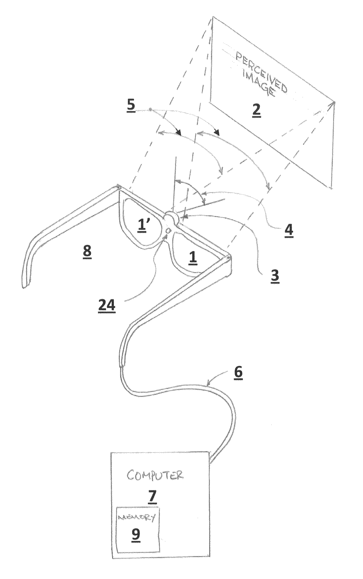
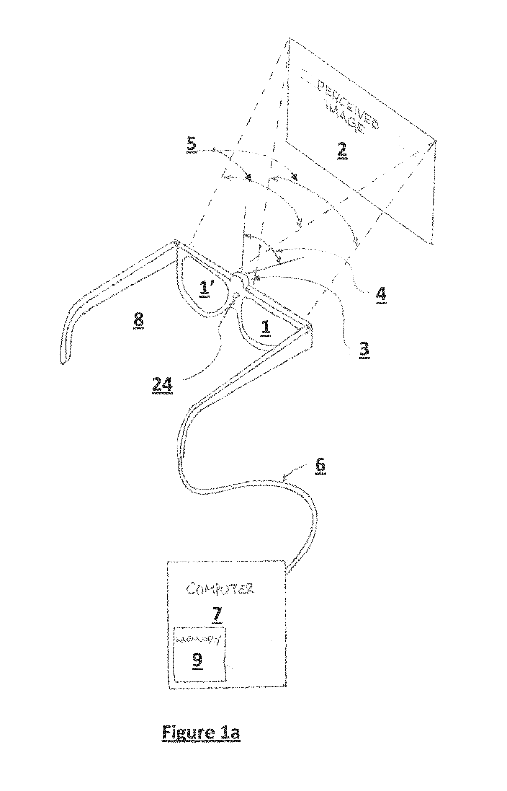
[0031]In brief overview and referring to FIG. 1a, the system in one embodiment includes a pair of eyeglass frames 8 or headmounted display and a processor 7. In this embodiment, the traditional transparent lenses in the eyeglasses frames 8, have been replaced with one or two display screens 1, 1′ (generally 1). Attached to the frame are one or more image capture devices 3, such as a camera. The electronics provide for image capture by the image capture device and transmission to the processor 7 by way of a wired or wireless link 6. The processor 7 not only receives images from the image capture device 3, but transmits the modified images back to the eyeglass frames 8 for display on one or both of the display screens 1, 1′.

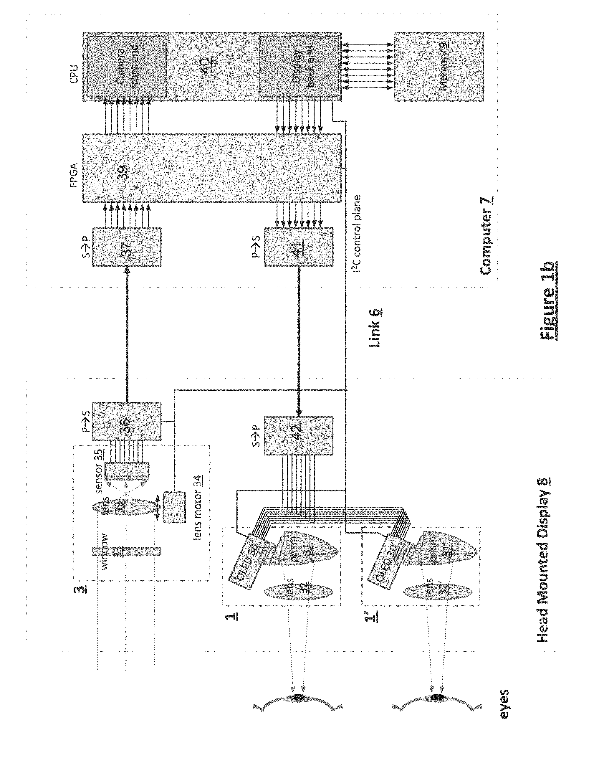
[0032]In more detail as shown in FIG. 1b, in various embodiments, the displays 1, 1′ in the eyeglass frames 8 include, in one embodiment, two Organic Light Emitting Diode (OLED) micro-displays for the left and right eyes 30, 30′, and two optical prisms 31, 31′ (gen...


PUM


Abstract

A method and apparatus of displaying a magnified image comprising obtaining an image of a scene using a camera with greater resolution than the display, and capturing the image in the native resolution of the display by either grouping pixels together, or by capturing a smaller region of interest whose pixel resolution matches that of the display. The invention also relates to a method whereby the location of the captured region of interest may be determined by external inputs such as the location of a person's gaze in the displayed unmagnified image, or coordinates from a computer mouse. The invention further relates to a method whereby a modified image can be superimposed on an unmodified image, in order to maintain the peripheral information or context from which the modified region of interest has been captured.

Description

CROSS REFERENCE TO RELATED APPLICATIONS[0001]This application claims priority to and the benefit of U.S. Provisional Application No. 61 / 262,766, filed Nov. 19, 2009. This application also is a continuation-in-part of U.S. application Ser. No. 12 / 060,964, filed Apr. 2, 2008. The entire disclosure of each of the above applications is incorporated by reference herein.FIELD OF THE INVENTION[0002]The invention relates generally to the field of displays and more specifically to the field of vision care.BACKGROUND OF THE INVENTION[0003]There are numerous applications for lightweight head-worn near-to-eye displays. These are commonly called Head Mounted Displays (HMD). HMDs display to the eye an electronically rendered image such that the wearer perceives that they are watching a sizeable electronic display at some distance in front of them. The applications that use such HMDs are numerous, including but not limited to virtual reality, electronic gaming, simulation environments such as for ...

Claims


Application Information

Patent Timeline
IPC IPC(8): H04N5/225G09G5/00H04N13/122
CPCG02B27/017G02B2027/0112G02B2027/0187G02B2027/0138G02B2027/014G02B2027/0118G06T7/11H04N13/239H04N13/383H04N13/117H04N13/344H04N13/346H04N13/122H04N23/69G02B27/0172G02B2027/0123G02B2027/0178G06F3/013
Inventor MUNGER, REJEAN J. Y. B.HILKES, ROBERT G.PERRON, MARCSOHI, NIRMAL
Owner ESIGHT CORP
Why Eureka
Try Eureka