Detachable optical fiber guides for splice connector installation tools, and related assemblies and methods
a technology of optical fiber guides and installation tools, which is applied in the direction of optical elements, manufacturing tools, instruments, etc., can solve the problems of unresolved devices and methods, less experienced technicians may lack the know-how and/or have difficulty in making high-quality termination in the field, and achieve the effect of reducing debris and damage to the optical fiber and improving the view of optical fibers
- Summary
- Abstract
- Description
- Claims
- Application Information
AI Technical Summary
Benefits of technology
Problems solved by technology
Method used
Image

Examples
Embodiment Construction
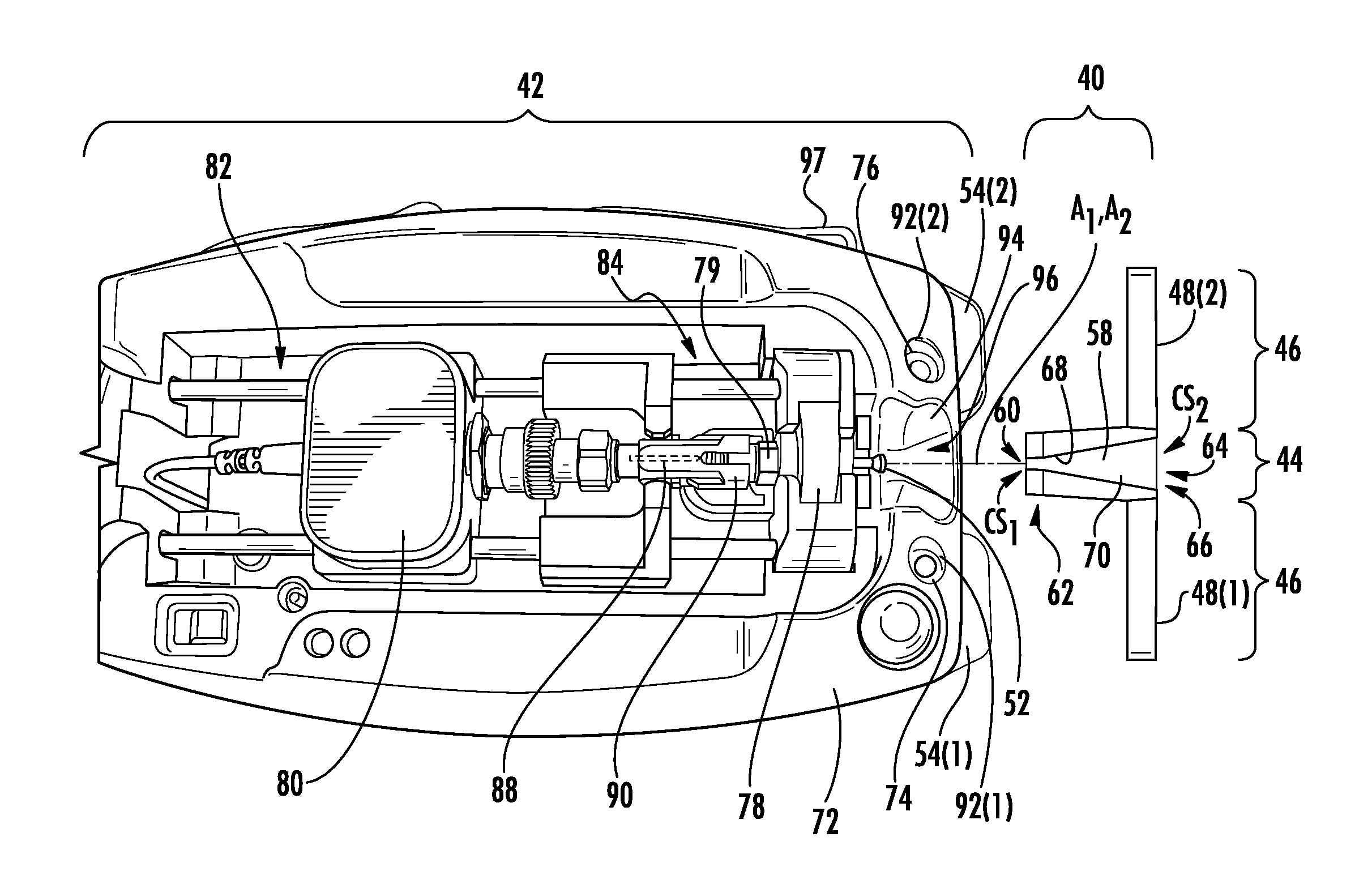
[0011]Embodiments disclosed herein include detachable optical fiber guides for splice connector installation tools, and related assemblies and methods. The detachable optical fiber guides may be employed to guide and / or self-align an optical fiber into a fiber optic connector disposed within a splice connector installation tool. As non-limiting examples, the detachable optical fiber guides may also be employed to better view the optical fiber during insertion, and also to reduce debris and damage to the optical fiber while being inserted into the fiber optic connector. The detachable optical fiber guides may include optional features to allow the detachable optical fiber guide to be installed and detached toollessly upon and from the splice connector installation tool for convenient installation, and subsequent removal. Optical fiber discussed herein includes one or more optical fibers whether disposed in a common cable jacket or disposed freely of each other outside a cable jacket....
PUM
| Property | Measurement | Unit |
|---|---|---|
| angle | aaaaa | aaaaa |
| angles | aaaaa | aaaaa |
| angle | aaaaa | aaaaa |
Abstract
Description
Claims
Application Information
 - R&D
- Intellectual Property
- Life Sciences
- Materials
- Tech Scout
- Unparalleled Data Quality
- Higher Quality Content
- 60% Fewer Hallucinations
Browse by: Latest US Patents, China's latest patents, Technical Efficacy Thesaurus, Application Domain, Technology Topic, Popular Technical Reports.
© 2025 PatSnap. All rights reserved.Legal|Privacy policy|Modern Slavery Act Transparency Statement|Sitemap|About US| Contact US: help@patsnap.com