
Systems and methods for identifying the circumferential positioning of electrodes of leads for electrical stimulation systems

a technology of electrical stimulation and electrodes, applied in the field of systems and methods for identifying the circumferential positioning of electrodes of leads for electrical stimulation systems, can solve problems such as unsatisfactory side effects

Active Publication Date: 2013-08-01
BOSTON SCI NEUROMODULATION CORP
View PDF5 Cites 284 Cited by
  • Summary
  • Abstract
  • Description
  • Claims
  • Application Information

AI Technical Summary

Benefits of technology

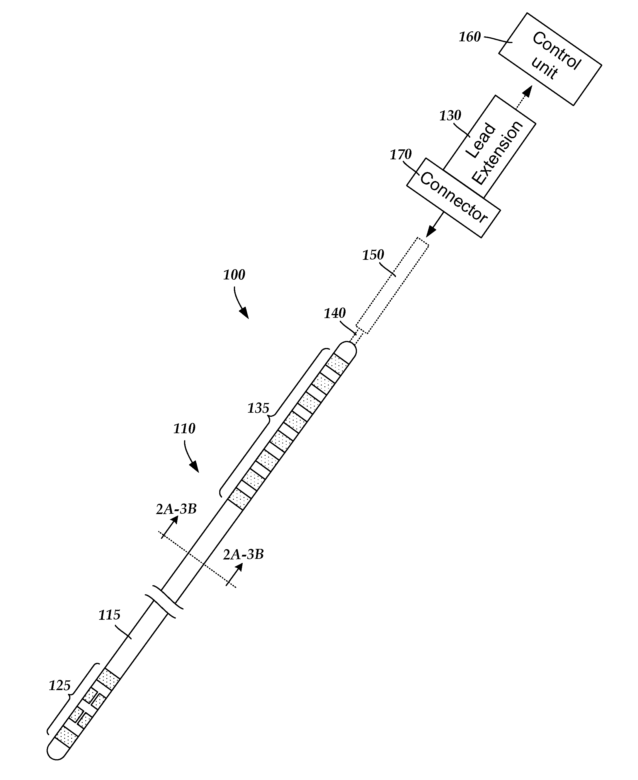
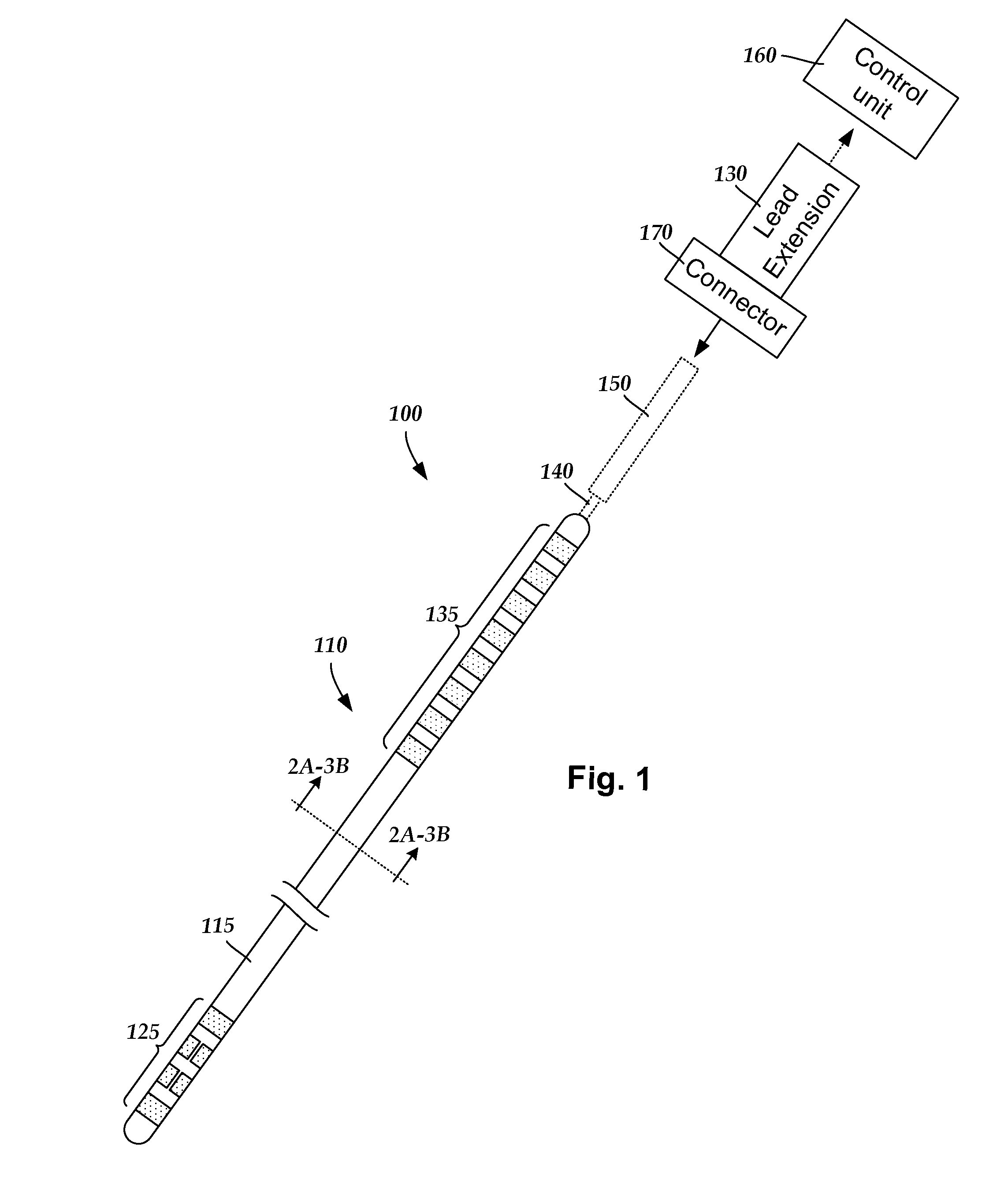
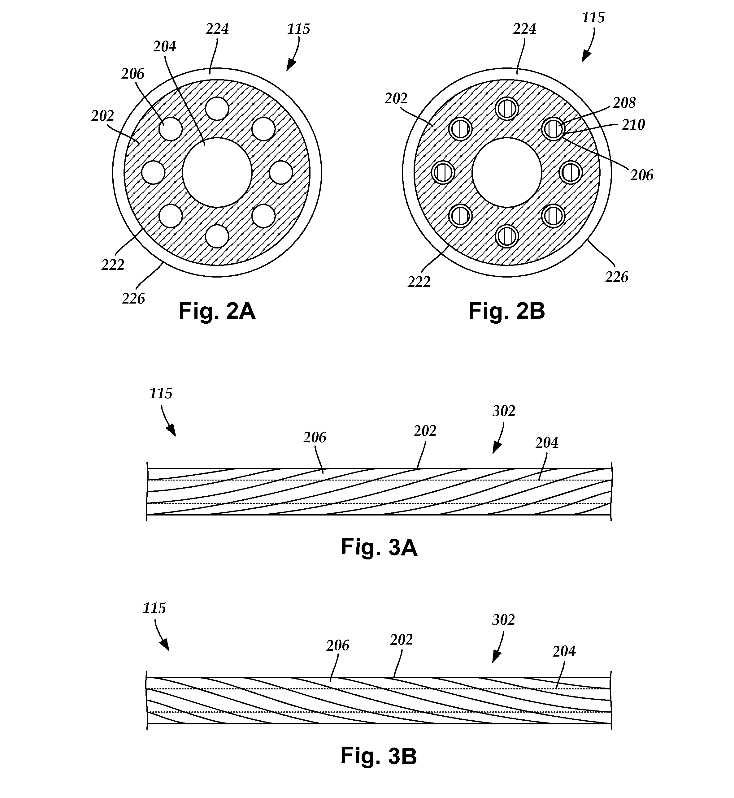
The patent describes a lead assembly for an electrical stimulation system that includes a lead body with electrodes along its distal end. These electrodes are arranged in a segmented pattern around the lead body. The lead also has terminals along its proximal end that are connected to the electrodes. The lead also includes a distal marker and a proximal marker that align with the segmented electrodes along its length. The system also includes a multi-lumen conductor guide with conductors inserted into its lumens, which are electrically connected to the electrodes. The guide has a twisted section with a helical pathway around its central lumen. An ablation is also formed along the guide's length to align with the marker. The technical effects of this patent include improved targeting of stimulation and easier identification of electrodes for programming and ablation.

Problems solved by technology

Consequently, undirected stimulation may result in unwanted stimulation of neighboring neural tissue, potentially resulting in undesired side effects.

Method used


Image

  • Systems and methods for identifying the circumferential positioning of electrodes of leads for electrical stimulation systems
  • Systems and methods for identifying the circumferential positioning of electrodes of leads for electrical stimulation systems
  • Systems and methods for identifying the circumferential positioning of electrodes of leads for electrical stimulation systems

Examples


Embodiment Construction

[0024]The invention is directed to the area of electrical stimulation systems and methods of making and using the systems. The present invention is also directed to electrical stimulation leads having electrodes and markers identifying the circumferential positioning of one or more of the electrodes, as well as methods of making and using the leads, electrodes, markers, and electrical stimulation systems.

[0025]A lead for deep brain stimulation may include stimulation electrodes, recording electrodes, or a combination of both. A practitioner may determine the position of the target neurons using the recording electrode(s) and then position the stimulation electrode(s) accordingly without removal of a recording lead and insertion of a stimulation lead. In some embodiments, the same electrodes can be used for both recording and stimulation. In some embodiments, separate leads can be used; one with recording electrodes which identify target neurons, and a second lead with stimulation el...


PUM

PropertyMeasurementUnit
cross-sectional diameteraaaaaaaaaa
lengthaaaaaaaaaa

Abstract

A lead assembly for an electrical stimulation system includes terminals disposed along a proximal end of a lead body and electrodes disposed along a distal end of the lead body. The electrodes include segmented electrodes. At least one distal marker is disposed along the distal end of the lead body. The distal marker identifies the circumferential position of at least one of the segmented electrodes along the lead body. The distal marker is aligned with at least one of the segmented electrodes along the longitudinal length of the lead body. At least one proximal marker is disposed along the proximal end of the lead body. The proximal marker is aligned with the distal marker along the longitudinal length of the lead body. The distal marker and the proximal marker are discontinuous with one another along the lead body.

Description

CROSS-REFERENCE TO RELATED APPLICATIONS[0001]This application claims the benefit under 35 U.S.C. §119(e) of U.S. Provisional Patent Application Ser. No. 61 / 591,046 filed on Jan. 26, 2012, which is incorporated herein by reference.FIELD[0002]The invention is directed to the area of electrical stimulation systems and methods of making and using the systems. The present invention is also directed to electrical stimulation leads having electrodes and markers identifying the circumferential positioning of one or more of the electrodes, as well as methods of making and using the leads, electrodes, markers, and electrical stimulation systems.BACKGROUND[0003]Electrical Stimulation can be useful for treating a variety of conditions. Deep brain stimulation can be useful for treating, for example, Parkinson's disease, dystonia, essential tremor, chronic pain, Huntington's disease, levodopa-induced dyskinesias and rigidity, bradykinesia, epilepsy and seizures, eating disorders, and mood disorde...

Claims


Application Information

Patent Timeline
Patent Type & Authority Applications(United States)
IPC IPC(8): A61N1/05H01R43/16A61N1/36
CPCA61N1/0534Y10T29/49208H01R43/16A61N1/3606
Inventor PIANCA, ANNE MARGARETCARCIERI, STEPHEN
Owner BOSTON SCI NEUROMODULATION CORP
Learn More