Floatable Constructions

a construction and basement technology, applied in the field of constructions, can solve the problems of threatening human life, substantial damage to property, and difficult to meet the needs of construction, and achieve the effects of reducing construction costs, reducing construction costs, and improving construction efficiency

Inactive Publication Date: 2013-08-08
LIZZANO
View PDF25 Cites 9 Cited by
  • Summary
  • Abstract
  • Description
  • Claims
  • Application Information

AI Technical Summary

Benefits of technology

[0028]The basement unit having the transfer platform provides a mechanically uniform platform upon which a superstructure of substantially any design and construction can be built. In some embodiments, the transfer platform may provide a driveway upon which vehicles may be parked. The weight of the superstructure is distributed across the base via the transfer platform, so there is no need for correspondence between the position of the load-bearing parts of the superstructure and the position of features within the basement structure. Thus, the present invention offers a

Problems solved by technology

In modern urban environments, the development and construction of large buildings for residential, commercial, leisure or industrial use can often be beset with problems.
Flooding can cause substantial damage to property and threaten human life, as the floods of 2007 in the UK showed.
Such damage is a consequence of previous decisions about l

Method used


Image

  • Floatable Constructions
  • Floatable Constructions
  • Floatable Constructions

Examples


first embodiment

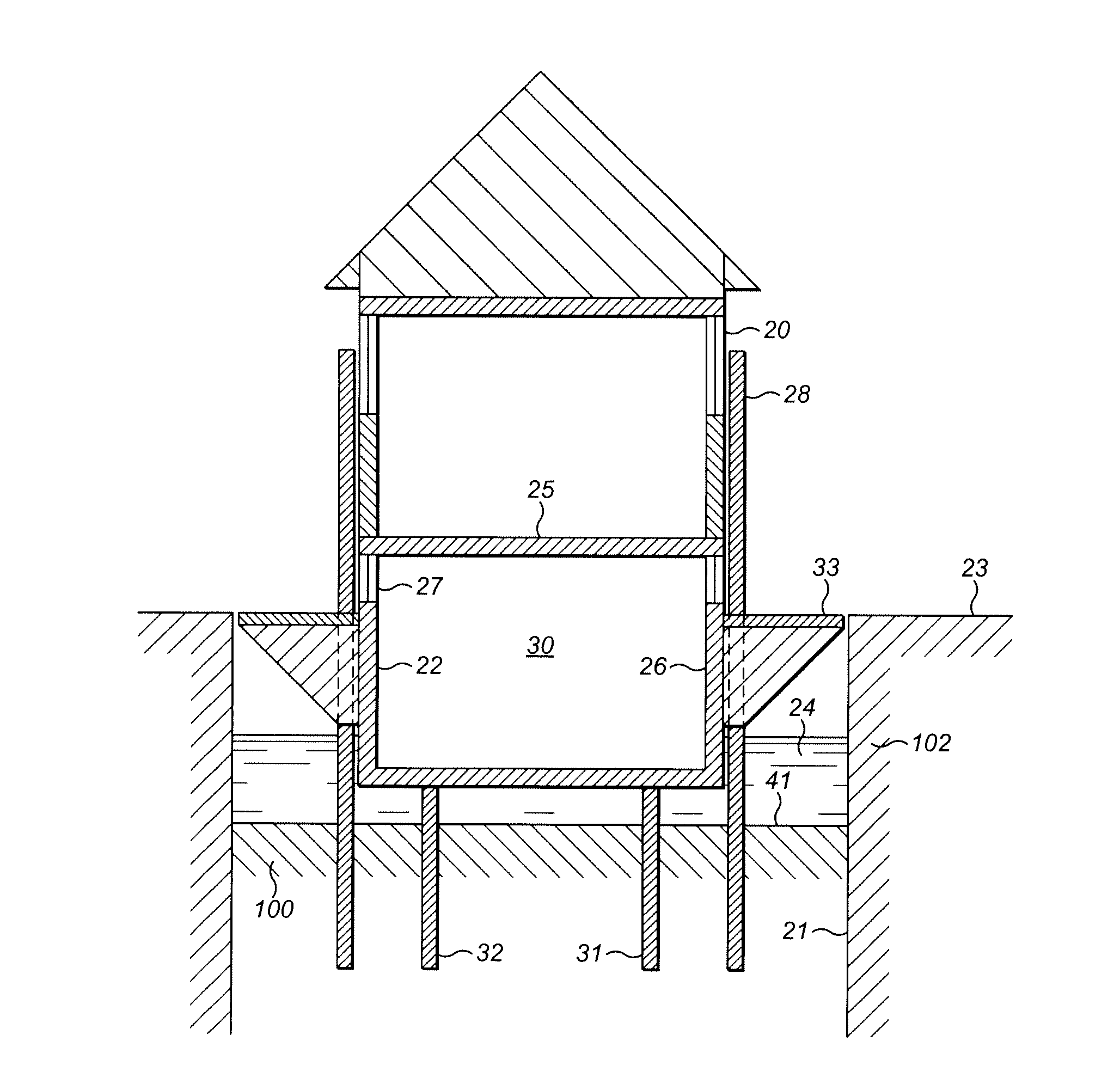
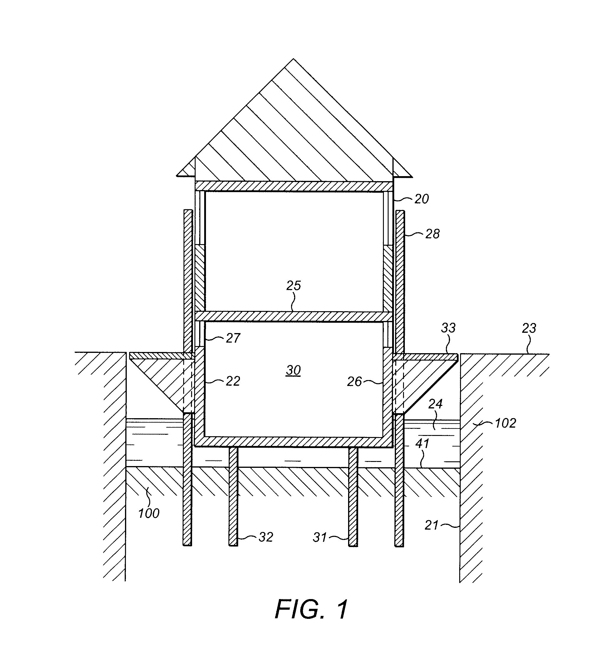
[0041]FIG. 1 shows a construction comprising: a pit 100; a buoyant basement unit 22; and a superstructure 20 built upon the basement unit 22.

[0042]Preferably, the basement unit 22 comprises a floor and external walls and one or more internal walls to define rooms in the basement level. Optionally, the floor is generally rectangular in plan, so that the rooms may be generally cuboidal.

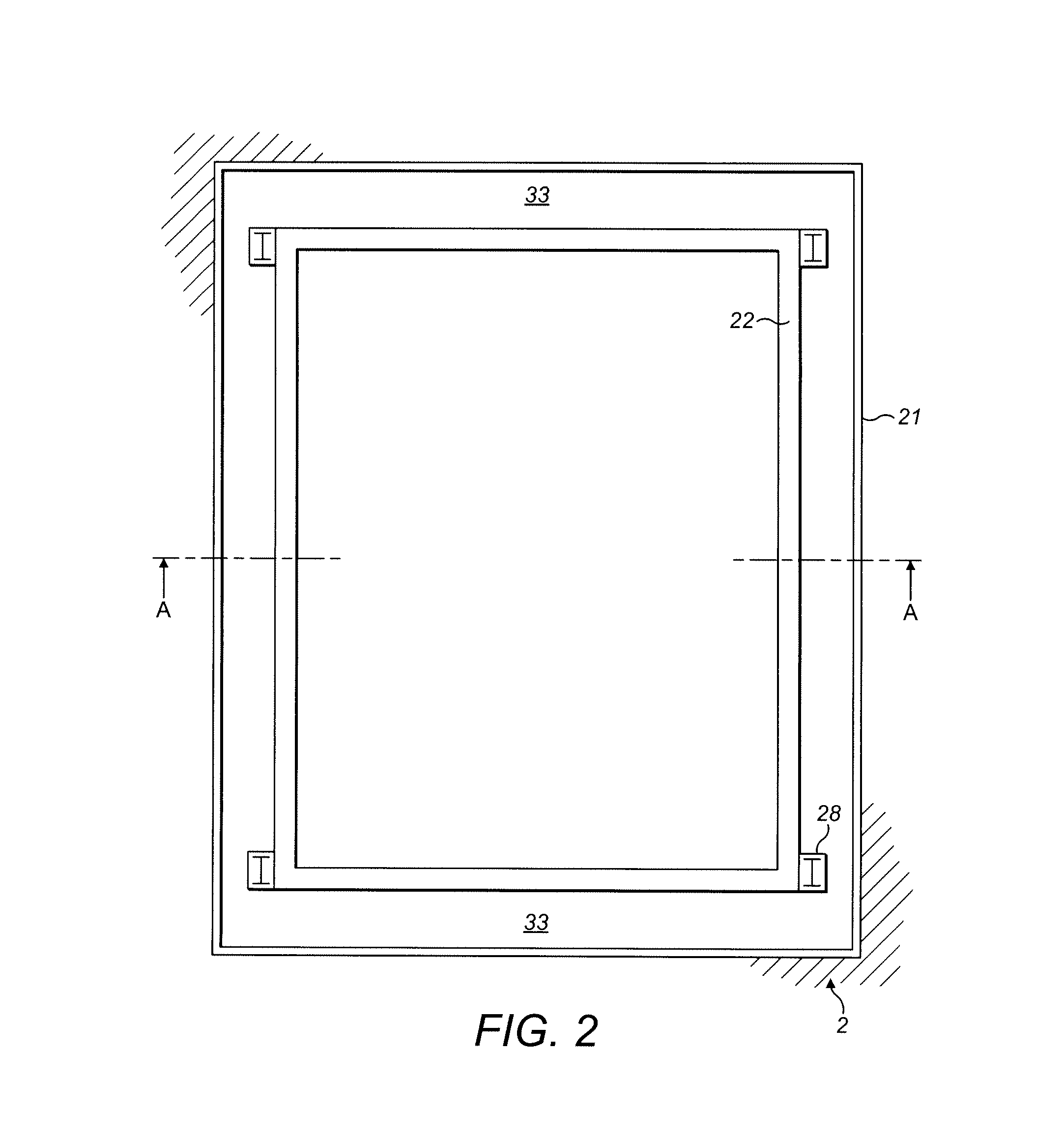
[0043]Preferably, an external floor 33 extends from the basement unit 22. Preferably, the external floor 33 is formed integrally with the basement unit 22. The external floor 33 may be polystyrene encased concrete, and can therefore act as an additional float. Optionally, the external floor 33 substantially surrounds the top of the basement. Thus, the external floor 33 can provide a walkway to ensure that nobody can fall into the excavated pit in which the basement unit 22 is located. Preferably, there is a gap of no more than 75 mm between the edge of the external floor 33 and the pit 100 when the base...

second embodiment

[0077]As shown in FIG. 5, a construction may include access to the pit 100 via a manhole 40 (preferably, a 600 mm×600 mm manhole with a replaceable cover). A metal ladder 41 between the floor of the pit 100 and the manhole 40 may be provided. This allow for maintenance and the clearance of any silt or debris which may accumulate in the pit 100.

[0078]Optionally, in either embodiment, a fence or handrail 60 is attached around the walkway.

[0079]Preferably, a barrier 61 extends down into the pit 100 from the basement unit 22 or, more preferably, from the outer edge of the external floor 33. This may be secured in place by one or more brackets 62 attached to the sheet piles 21.

[0080]Optionally, the barrier 61 may extend past the external floor 33 to form the fence or hand rail 60.

[0081]FIG. 6 depicts the construction in a raised position when the water level 50 has risen above ground level 23. In this position, the barrier 61 can prevent debris from entering the pit 100.

[0082]The barrier...


PUM


Abstract

A plurality of floatable constructions are provided, the constructions including a floating base for a building, the base having at least one buoyant basement unit defining a basement level, and a reinforced concrete transfer platform atop the basement unit. The basement level can provide habitable or functional space for the building, and the transfer platform has at least one access opening giving access to the basement level which is enhanced by windows for light and ventilation. Methods and means of tying modular components of the structures together, and materials suitable for manufacturing such ties, are also provided.

Description

CROSS-REFERENCE TO RELATED APPLICATIONS[0001]Pursuant to 35 U.S.C. 119(a), the instant application claims priority to prior United Kingdom application number GB 1201877.6, filed Feb. 2, 2012.FIELD OF THE INVENTION[0002]The present invention relates to constructions that are normally at rest on the ground or some form of solid support, but can float during periods of flooding. In particular, but not exclusively, the invention relates to constructions having a buoyant basement structure which support conventional buildings.BACKGROUND OF THE INVENTION[0003]In modern urban environments, the development and construction of large buildings for residential, commercial, leisure or industrial use can often be beset with problems.[0004]For example, a site in UK may have been previously developed, but with a change of legislation the land may now be classified as within a flood zone, e.g. Planning Policy Statement 25 (PPS 25) & the Development and Flood Risk Practice Guide dated June 2008. PPS...

Claims


Application Information

Patent Timeline
IPC IPC(8): B63B35/44E04H9/14
CPCB63B35/44E02D27/06B63B2035/4426E04H9/145Y02A30/00Y02A50/00E04B1/34363
Inventor NELSON, CARL RICHARD
Owner LIZZANO
Why Eureka
Try Eureka