Method and apparatus for deactivating a hydraulic device that is leaking hydraulic oil

Active Publication Date: 2013-08-08
GULFSTREAM SERVICES INC
View PDF12 Cites 6 Cited by
  • Summary
  • Abstract
  • Description
  • Claims
  • Application Information

AI Technical Summary

Benefits of technology

The present invention provides a portable system that can be easily connected to a hydraulic power unit to quickly stop fluid leakage. The system can shut down the pump or other parts of the unit based on the amount of fluid loss. The apparatus can shut down the pump, stop fluid flow, and / or close a valve to prevent fluid from leaking or flowing out of the system. The method and apparatus are simple, effective, and can quickly stop leaks in hydraulic systems.

Problems solved by technology

Leakage of hydraulic fluid in a marine environment is a serious and potentially very costly problem.

Method used


Image

  • Method and apparatus for deactivating a hydraulic device that is leaking hydraulic oil
  • Method and apparatus for deactivating a hydraulic device that is leaking hydraulic oil
  • Method and apparatus for deactivating a hydraulic device that is leaking hydraulic oil

Examples


example 1

[0109]An exemplary hydraulic cylinder could have the following dimensions:

[0110]Cylinder bore=8 inches (20 cm), cylinder rod=6 inches (15 cm), cylinder stroke=20.5 inches (52 cm)

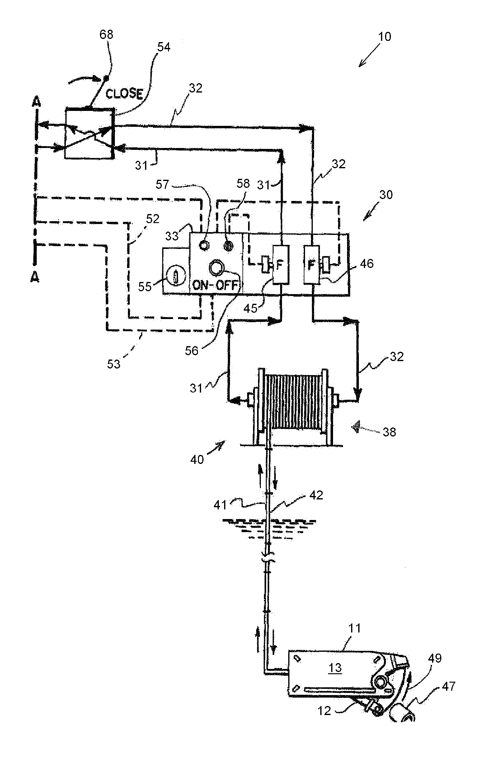
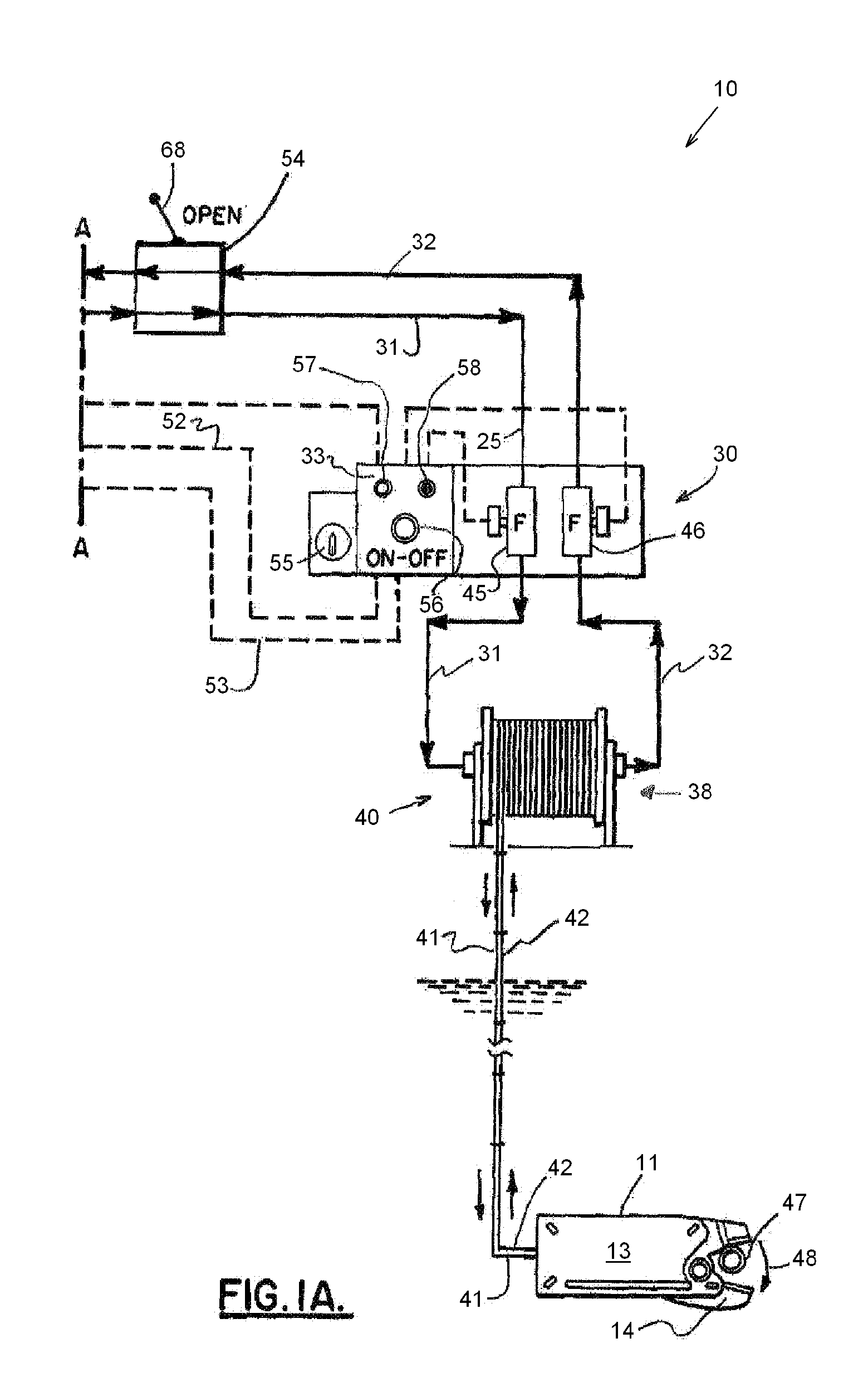
[0111]For this system, shutdown occurs when the difference in volume entering and exiting the cylinder is different from the ratio between the cylinder piston area and the cylinder annulus area. The annulus area is equal to the piston area minus the rod area. The computer or controller 33 which is part of the control system 30 compensates for this difference in volume, continuously calculating the ratio based upon input from the flow meters 45, 46. The computer or controller 33 can be a commercially available “Plus +1” controller available from Sauer-Danfoss (e.g. models MC024-010 or MC024-012).

[0112]The piston end volume is equal to the Cylinder Piston Area times the Cylinder Stroke

[0113]Cylinder piston area=Piston Diameter squared times a constant of (0.7845)

[0114]8″ (20 cm) squared (x) 0.7854=50.26 sq. in...


PUM


Abstract

A method of deactiving an underwater hydraulic device provides a hydraulic device that is capable of being operated under water, the device having a hydraulic cylinder with a pushrod and a piston. The device is lowered below a water surface with a hose reel that is located at the water surface area such as on a marine vessel. The hose reel includes first and second hydraulic hoses that connect to the cylinder on opposing sides of the piston. Fluid flow in the first and second hydraulic hoses is continuously monitored. The ratio of the volume of fluid flowing into the cylinder from one side of the piston to the volume of fluid flowing into the cylinder from the other side of the cylinder is continuously calculated with a computer or controller. The hydraulic device is deactivated if the ratio varies from a preset value. One embodiment includes a plurality of flow meters for measuring fluid flow to and from one or more hydraulicly powered apparatuses. In one embodiment outputs of the flow meters are analyzed to determine if the hydraulic system has a leak, and if a leak is detected, a warning is issued and / or one or more of the connected hydraulically powered apparatuses are shut down, and / or the hydraulic power supply is shut down.

Description

CROSS-REFERENCE TO RELATED APPLICATIONS[0001]This is a non provisional patent application of U.S. Provisional Patent Application Ser. No. 61 / 586,530, filed 13 Jan. 2012, and U.S. Provisional Patent Application Ser. No. 61 / 727,324, filed 16 Nov. 2012.[0002]Priority of U.S. Provisional Patent Application Ser. No. 61 / 586,530, filed 13 Jan. 2012, and U.S. Provisional Patent Application Ser. No. 61 / 727,324, filed 16 Nov. 2012, each of which is hereby incorporated herein by reference, is hereby claimed.STATEMENT REGARDING FEDERALLY SPONSORED RESEARCH OR DEVELOPMENT[0003]Not applicableREFERENCE TO A “MICROFICHE APPENDIX”[0004]Not applicableBACKGROUND OF THE INVENTION[0005]1. Field of the Invention[0006]The present invention relates to an improved method and apparatus for underwater device leak detection in a hydraulic system or device that includes a hydraulic ram. More particularly, the present invention relates to a method of detecting leaks (e.g. broken or cut hose or leaking seal or fi...

Claims


Application Information

Patent Timeline
IPC IPC(8): F16K17/24
CPCF16K17/24F15B20/005F15B19/005G01M3/26F15B2211/632F15B2211/8636Y10T137/0379Y10T137/7722
Inventor NAQUIN, JOEY
Owner GULFSTREAM SERVICES INC
Why Eureka
Try Eureka