Electromagnetic field assisted self-assembly with formation of electrical contacts

a technology of electrical contacts and self-assembly, which is applied in the direction of soldering apparatus, sustainable manufacturing/processing, final product manufacturing, etc., to achieve the effect of reducing the repulsive for

Inactive Publication Date: 2013-08-08
UNITED STATES OF AMERICA THE AS REPRESENTED BY THE SEC OF THE ARMY
View PDF10 Cites 13 Cited by
  • Summary
  • Abstract
  • Description
  • Claims
  • Application Information

AI Technical Summary

Benefits of technology

[0005]Embodiments of the present invention include methods and apparatus for self-assembling a part on a substrate. In some embodiments, a method of self-assembling a part on a substrate includes placing a substrate into a first fluid, the substrate including a first binding site capable of generating a first electromagnetic field and having a first shaped surface with a first droplet conformably disposed on the first shaped surface, wherein the first droplet is immiscible in the first fluid; placing a part into the first fluid, the part having a second binding site capable of generating a second electromagnetic field and having a second shaped surface with a second droplet conformably disposed on the second shaped surface, wherein the sec

Problems solved by technology

Methods of self-assembly may include gravitational, capillary, or magnetic forces, each of which has limitations related to assembling one or m

Method used


Image

  • Electromagnetic field assisted self-assembly with formation of electrical contacts
  • Electromagnetic field assisted self-assembly with formation of electrical contacts
  • Electromagnetic field assisted self-assembly with formation of electrical contacts

Examples


Embodiment Construction

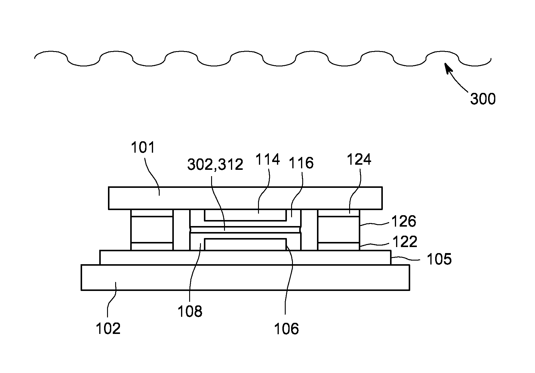
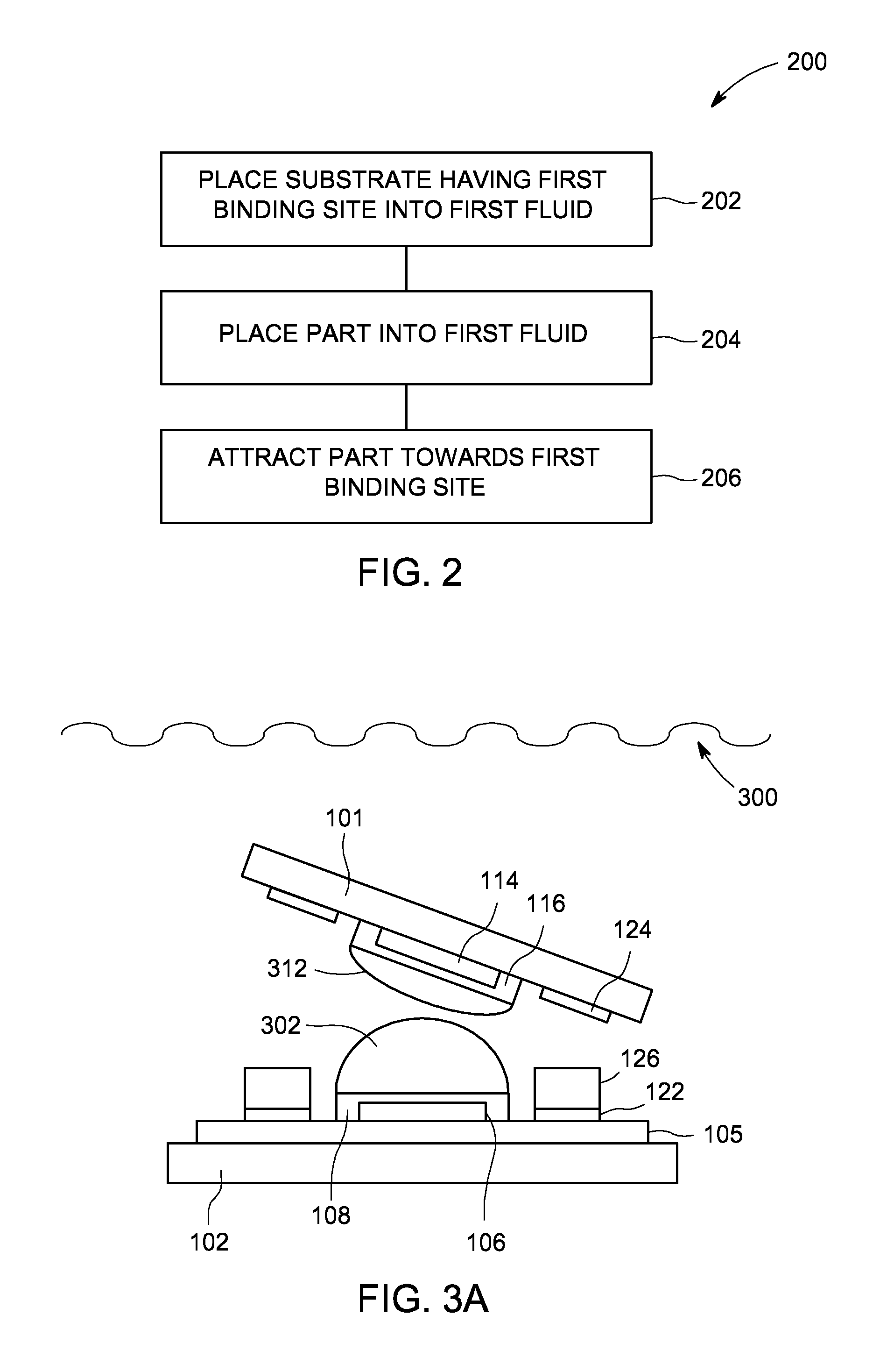
[0012]Embodiments of the present invention comprise methods and apparatus for self-assembling a part on a substrate. The inventive methods and apparatus advantageously facilitate the self-assembly of the part onto the substrate such that the part and the substrate are aligned during the self-assembly process.

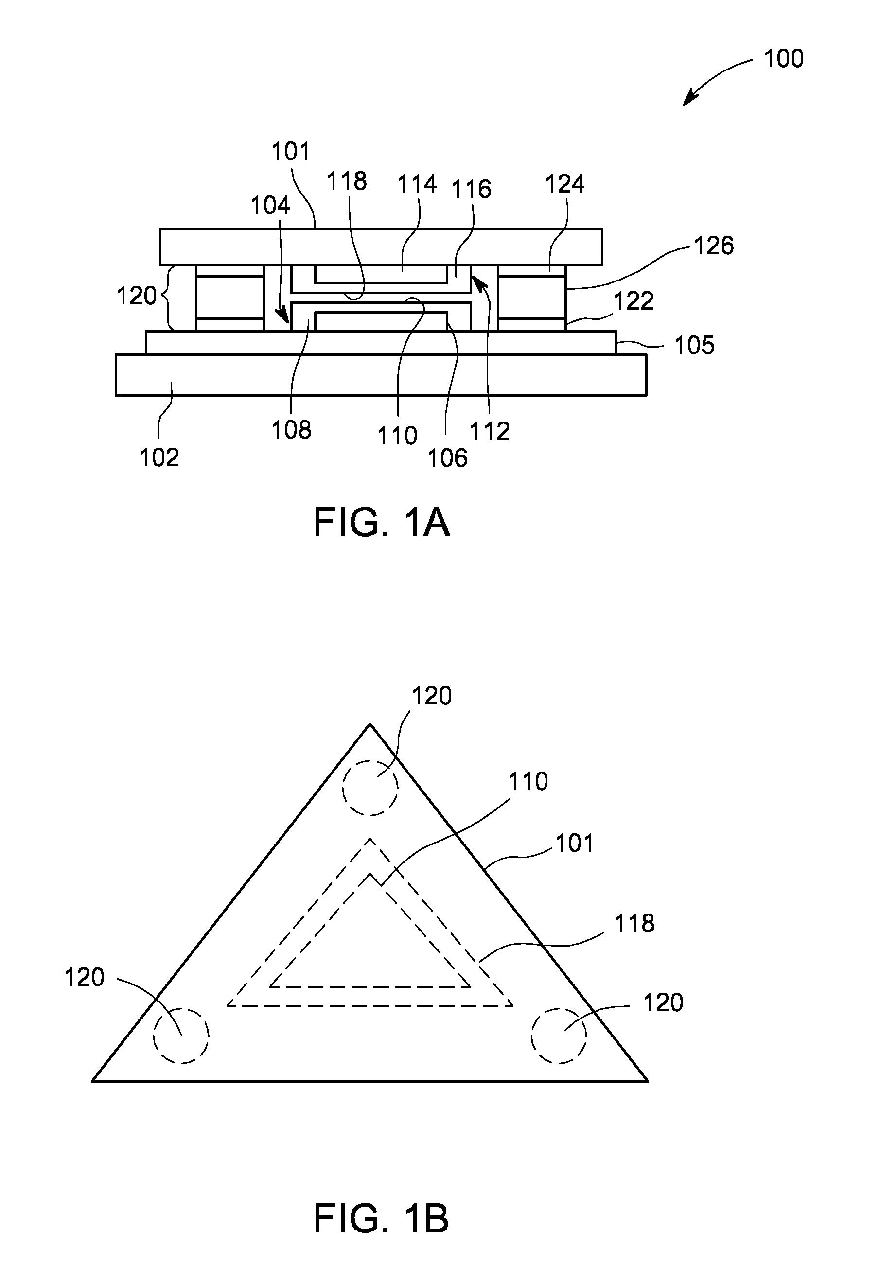
[0013]FIG. 1A depicts a side schematic view of an article 100 in accordance with some embodiments of the present invention. The article 100 includes a part 101 and a substrate 102. For example, the substrate 102 may include one or more of silicon (Si), glass, plastic, or other suitable substrate materials. The substrate 102 includes a first binding site 104. As illustrated in FIG. 1, an electrically conductive layer 105 may be disposed between the substrate 102 and the first binding site 104. For example, the electrically conductive layer 105 may include one or more of gold (Au), copper (Cu), aluminum (Al), or other suitable conductive materials.

[0014]The first binding site 104 ...


PUM

PropertyMeasurementUnit
Boiling pointaaaaaaaaaa
Hydrophobicityaaaaaaaaaa
Electromagnetic fieldaaaaaaaaaa

Abstract

A method and apparatus for self-assembling a part on a substrate are disclosed herein. In some embodiments, a method includes placing a substrate having a first binding site capable of generating a first magnetic field and having a first shaped surface with a first droplet conformably disposed thereon into a first fluid; placing a part having a second binding site capable of generating a second magnetic field and having a second shaped surface with a second droplet conformably disposed on the second shaped surface into the first fluid; and attracting the part towards the first binding site such that an equilibrium is formed between an attractive force and a repulsive force such that the part is free to rotate about the first binding site to minimize the repulsive force when the first and second shaped surfaces rotate into an alignment causing the part to aligned with the first binding site.

Description

GOVERNMENT INTEREST[0001]Governmental Interest—The invention described herein may be manufactured, used and licensed by or for the U.S. Government.FIELD OF INVENTION[0002]Embodiments of the present invention generally relate to methods of self-assembly and apparatus for accomplishing the same.BACKGROUND OF THE INVENTION[0003]Self-assembly is a promising technique to overcome limitations, for example, with integrating, packaging, and / or handling individual electronic components that have critical dimensions of about 300 microns or below. Methods of self-assembly may include gravitational, capillary, or magnetic forces, each of which has limitations related to assembling one or more electronic components on a substrate, for example, such as aligning one or more electronic components with a binding site on the substrate.[0004]The inventor has provided improved methods and apparatus for self-assembly.BRIEF SUMMARY OF THE INVENTION[0005]Embodiments of the present invention include method...

Claims


Application Information

Patent Timeline
IPC IPC(8): H05K1/16H05K13/04
CPCH01L24/95H01L2224/81085H05K3/303H05K3/3436H05K2201/083H05K2203/048H05K2203/0776H05K2203/104H01L2224/95085H01L2924/10156H01L2224/95001H01L2224/81455H01L2224/81447H01L2224/81444H01L2224/81002H01L2224/29111H01L2224/13111H01L2224/05655H05K13/0015H05K13/027H05K13/04H05K2203/04H01L2224/95133H01L2924/0132H01L24/05H01L24/13H01L24/81H01L2224/0401H01L2224/05644H01L2224/05647H01L2924/01082H01L2924/01083H01L2924/0105H01L2924/15788H01L2224/81143Y02P70/50H01L2224/95146H01L2924/00B23K1/0016B23K1/20
Inventor MORRIS, CHRISTOPHER
Owner UNITED STATES OF AMERICA THE AS REPRESENTED BY THE SEC OF THE ARMY
Why Eureka
Try Eureka