Electroformed sheath

a technology of electro-formed sheaths and sheaths, which is applied in the direction of liquid fuel engines, cell components, lighting and heating apparatuses, etc., can solve the problems of difficult manufacturing of sheaths having certain characteristics (e.g., certain geometries, dimensions, etc.)

Inactive Publication Date: 2013-08-08
RAYTHEON TECH CORP
View PDF9 Cites 36 Cited by
  • Summary
  • Abstract
  • Description
  • Claims
  • Application Information

AI Technical Summary

Benefits of technology

[0008]According to another aspect of the present invention, an airfoil of a gas turbine engine is provided. The airfoil includes a sheath body and a mandrel insert. The sheath body includes a leading edge. The sheath body includes a pressure side wall and an opposed suction side wall of the sheath body, which side walls meet at the leading edge and extend away from the leading edge to define a cavity between the side wall

Problems solved by technology

Electroforming techniques work reasonably well, but can also have constraints that make it difficult

Method used


Image

  • Electroformed sheath
  • Electroformed sheath
  • Electroformed sheath

Examples


Embodiment Construction

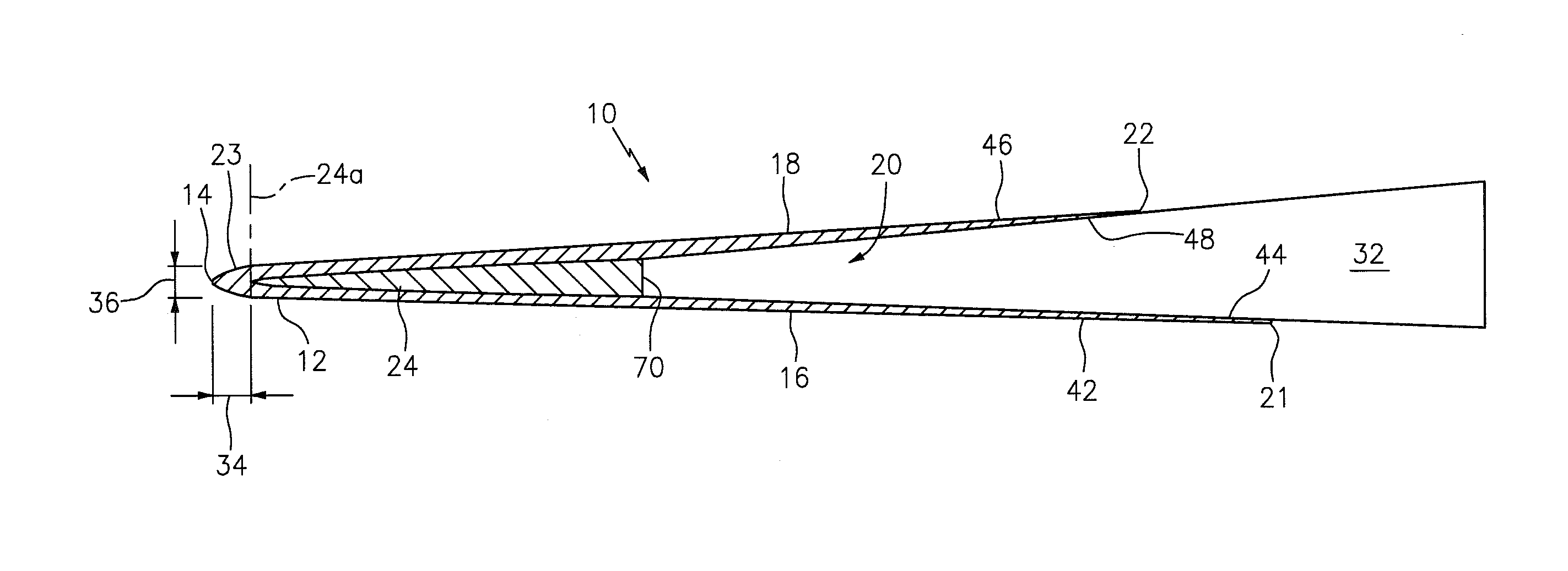
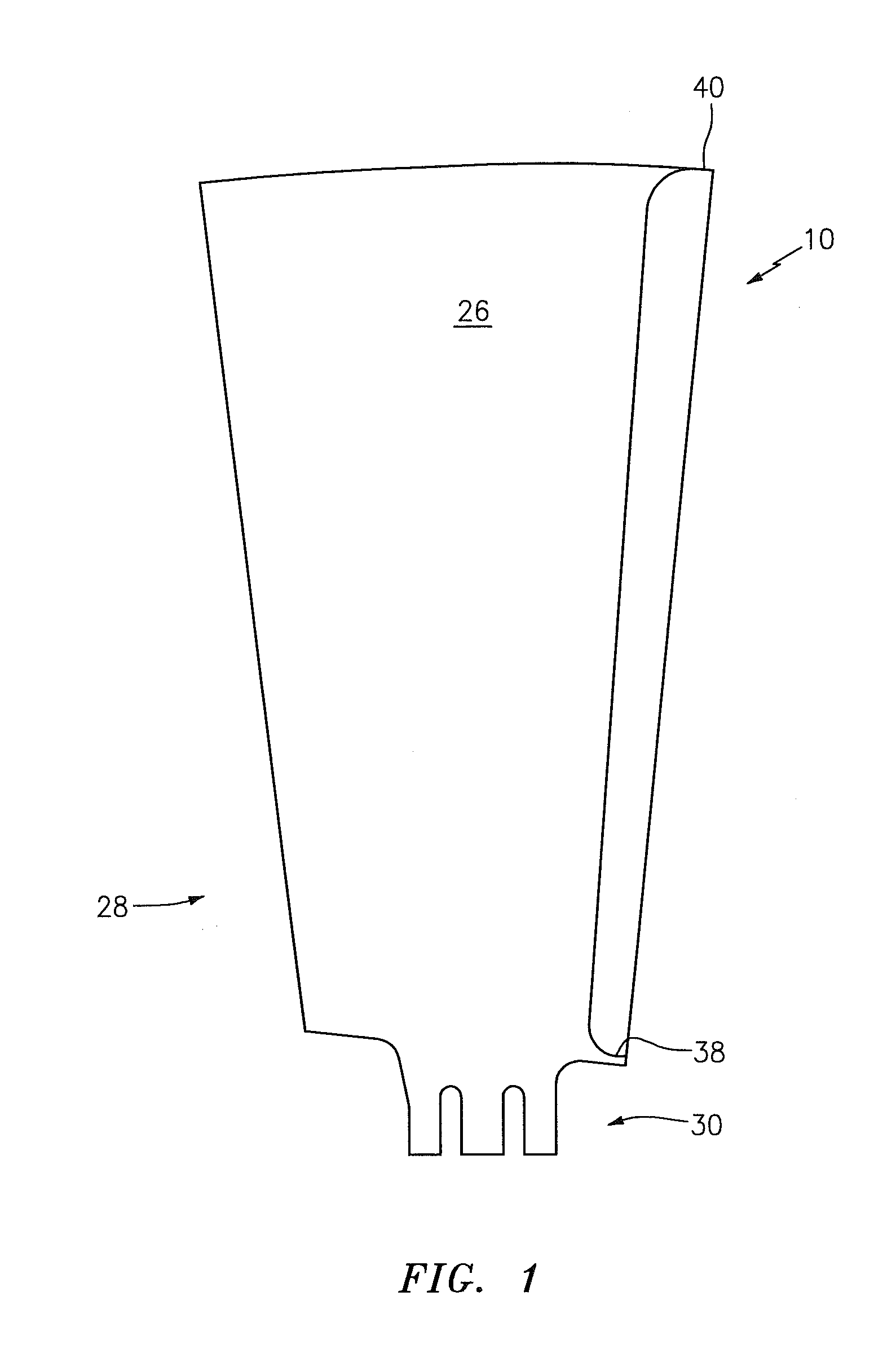
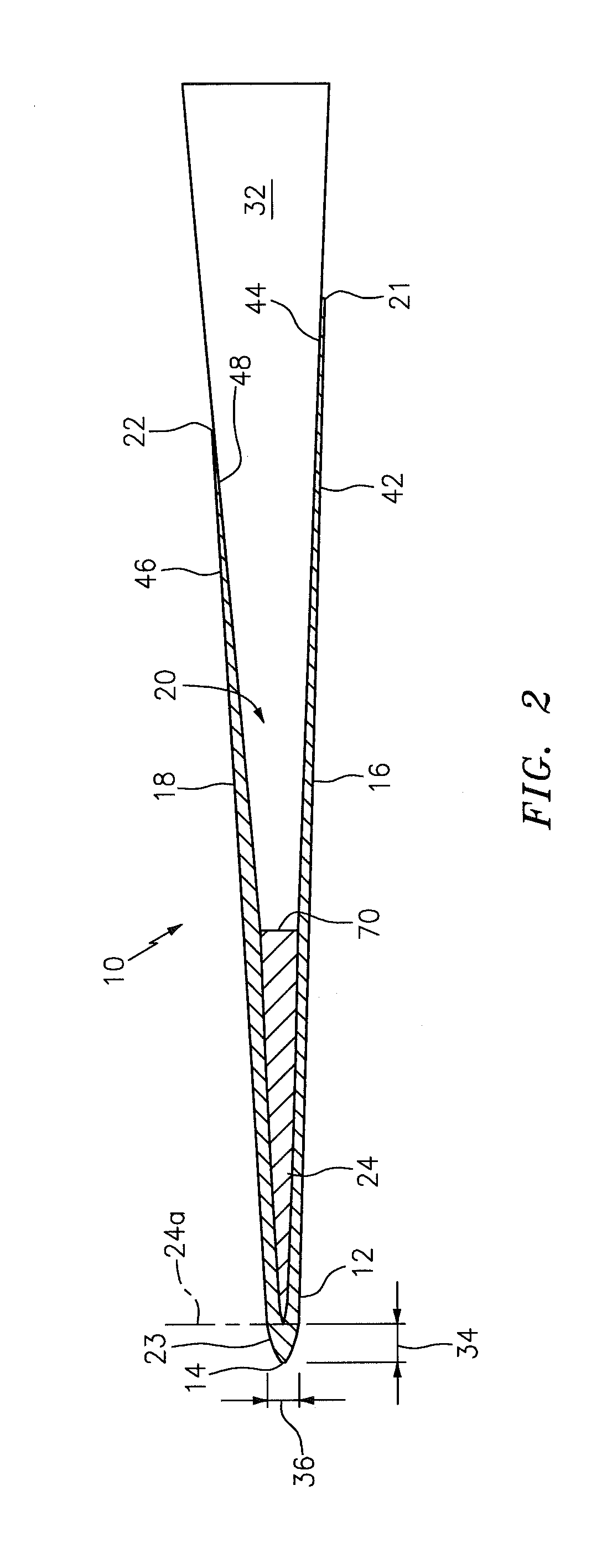
[0027]Referring to the drawings in detail, an electroformed sheath of the present invention is shown in FIGS. 1-3 and generally designated by the reference numeral 10. As best seen in FIG. 2, the electroformed sheath 10 includes a sheath body 12 having a leading edge 14, a pressure side wall 16 and an opposed suction side wall 18. The side walls 16, 18 meet at the leading edge 14 and extend away from the leading edge 14 to define a sheath cavity 20. The side walls 16, 18 end at a pressure side wall trailing edge 21 and a suction side wall trailing edge 22, respectively. The sheath body 12 also includes a head section 23 extending between the leading edge 14 and the cavity 20. The electroformed sheath 10 also includes a mandrel insert 24 positioned between the pressure and suction side walls 16, 18 of the sheath body 12. FIG. 1 shows the electroformed sheath 10 affixed to an airfoil 26 of a fan blade 28. The fan blade 28 includes a root 30 that is configured to engage a gas turbine e...


PUM

PropertyMeasurementUnit
Lengthaaaaaaaaaa
Thicknessaaaaaaaaaa
Electrical conductivityaaaaaaaaaa

Abstract

An electroformed sheath for protecting an airfoil includes a sheath body and a mandrel insert is provided. The sheath body includes a leading edge. The sheath body includes a pressure side wall and an opposed suction side wall, which side walls meet at the leading edge and extend away from the leading edge to define a cavity between the side walls. The sheath body includes a head section between the leading edge and the cavity. The mandrel insert is positioned between the pressure side and suction side walls, and includes a generally wedge-shaped geometry. A method for protecting an airfoil includes: 1) securing a mandrel insert to a mandrel; 2) electroplating a sheath body onto the mandrel and the mandrel insert; 3) removing the mandrel from the sheath body so that a sheath cavity is defined within the sheath body; and 4) securing the airfoil within the sheath cavity.

Description

BACKGROUND OF THE INVENTION[0001]1. Technical Field[0002]The present invention relates to electroformed parts in general, and to an electroformed sheath for protecting a leading edge of an airfoil of a gas turbine engine in particular.[0003]2. Background Information[0004]Historically, airfoils of gas turbine engines have been designed to provide adequate mechanical strength and durability to protect themselves from erosion and foreign object damage, and especially from damage as a result of leading edge impact with birds, ice, stones, sand, rain and other debris. Protective sheaths are often used to protect the leading edge.[0005]It is known to manufacture protective sheaths using electroforming techniques, as described, e.g., in U.S. Pat. No. 5,908,285, which is incorporated herein by reference. Electroforming techniques work reasonably well, but can also have constraints that make it difficult to manufacture sheaths having certain characteristics (e.g., certain geometries, dimensi...

Claims


Application Information

Patent Timeline
IPC IPC(8): C25D1/04C25D7/06
CPCC25D1/02F01D5/147F04D29/324F05D2230/30F05D2230/90F05D2240/303F05D2300/603F28F1/40C25D1/00
Inventor PARKOS, JR., JOSEPHHANSEN, JAMES O.HERTEL, CHRISTOPHER A.MURPHY, ANDREW J.PHILLIPS, ASHLEY P.ABRAHAM, JAY T.
Owner RAYTHEON TECH CORP
Why Eureka
Try Eureka