Electric machine

a technology of electric motors and electric motors, applied in the direction of dynamo-electric machines, electrical devices, windings, etc., can solve the problem that the electrical connection cannot be represented easily, and achieve the effect of simple manner

a technology of electric motors and electric motors, applied in the direction of dynamo-electric machines, electrical devices, windings, etc., can solve the problem that the electrical connection cannot be represented easily, and achieve the effect of simple manner

US20130200757A1Active Publication Date: 2013-08-08ROBERT BOSCH GMBH +1

Image

  • Electric machine
  • Electric machine
  • Electric machine

Examples


Embodiment Construction

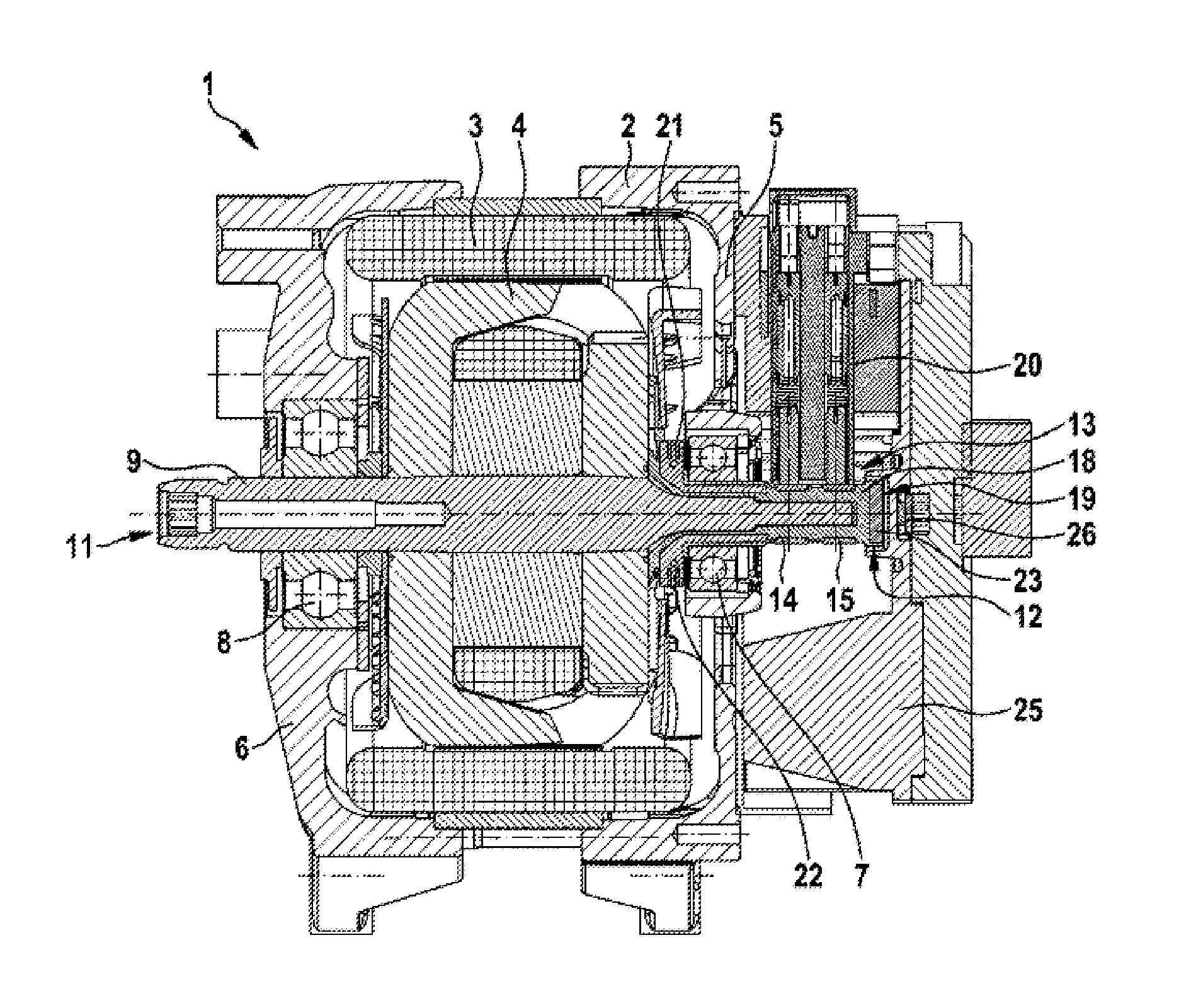
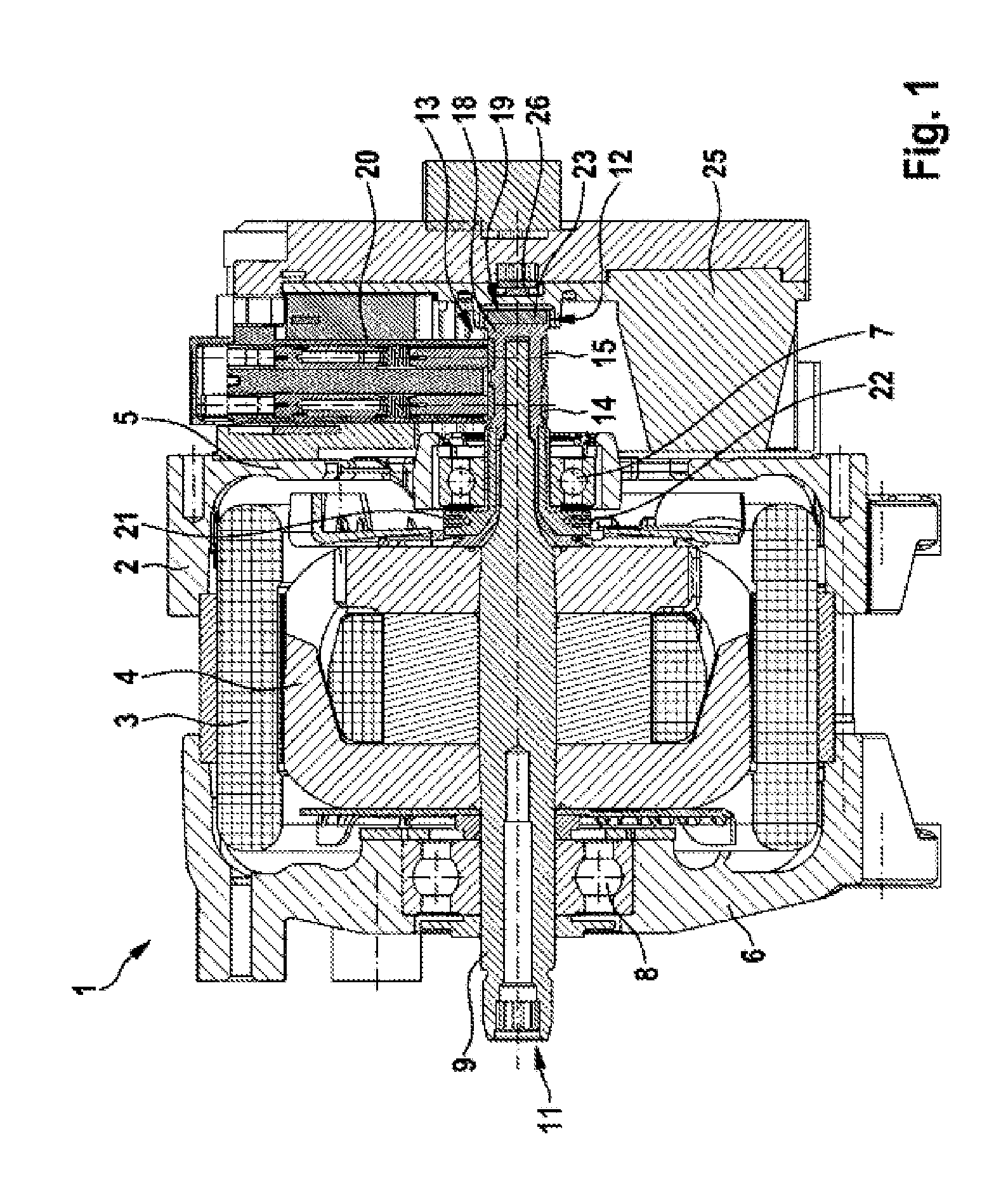
[0020]FIG. 1 shows, in a simplified longitudinal sectional illustration, an electric machine 1, which can be used as a drive assembly in a motor vehicle. The electric machine 1 has a housing 2, in which a stator 3 and a rotor 4, which in this case is in the form of a claw-pole rotor, are arranged, with the stator mounted fixedly and the rotor mounted rotatably. The housing 2 has two mutually opposite end plates 5, 6 which each bear a rolling bearing 7, 8, which in this case is in the form of a ball bearing. The rolling bearings 7, 8 are used for the low-friction bearing arrangement of a rotor shaft 9, which bears the rotor 4 and which extends axially through the housing 2.

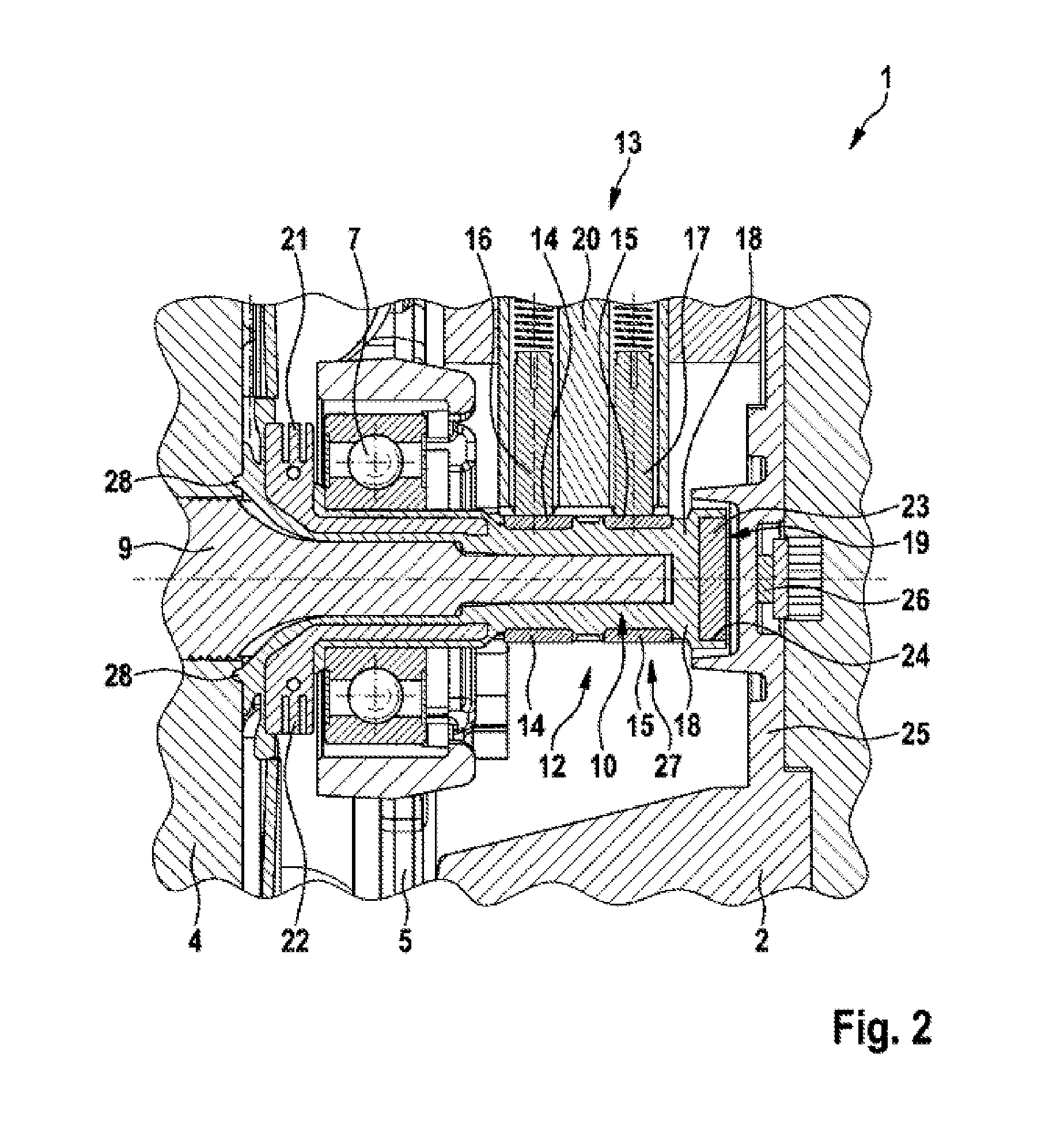
[0021]At one end, the rotor shaft 9 has a coupling element 11, which is used for connecting the rotor shaft 9 to a gear mechanism, for example, in rotationally fixed fashion. In this case, the coupling means 11 is in the form of internal toothing. A slip ring device 13 is associated with that end 10 of the rotor sh...


PUM


Abstract

An electric machine (1), in particular for a drive apparatus for a motor vehicle, comprising a rotor shaft (9), which is mounted rotatably in a housing (2), comprising a slip ring device (13), which has at least two slip rings (14, 15) arranged in rotationally fixed fashion on the rotor shaft (9) and at least two sliding contacts (16, 17), which are arranged in the housing (2) and interact with in each case one of the slip rings (14, 15), and comprising a rotation angle detection device, which has at least one rotation angle encoder (23) arranged on the rotor shaft (9) and at least one rotation angle sensor (26) arranged in the housing for detecting the rotation angle encoder (23).

Description

BACKGROUND OF THE INVENTION[0001]The invention relates to an electric machine, in particular for a drive apparatus for a motor vehicle, comprising a rotor shaft, which is mounted rotatably in a housing, comprising a sliding device, which has at least two slip rings arranged in rotationally fixed fashion on the rotor shaft and at least two sliding contacts, which are arranged in the housing and interact with in each case one of the slip rings, and comprising a rotation angle detection device, which has at least one rotation angle encoder arranged on the rotor shaft and at least one rotation angle sensor arranged in the housing for detecting the rotation angle encoder,[0002]Electric machines of the type mentioned at the outset are known from the prior art. In general, an electric machine has a rotor, which is mounted on a rotor shaft and which interacts with a stator arranged in a housing bearing the rotor shaft. In particular when the electric machine is intended to be operated as a ...

Claims


Application Information

Patent Timeline
08 Aug 2013
Publication
US20130200757A1
IPC
H02K13/00; H02K11/00
CPC
H02K11/0015; H02K11/0021; H02K3/528; H02K29/08; H02K13/02; H02K13/003; H02K11/215
Inventors
SCHROEDER, BERND; MAUS, CHRISTIAN