Assembly, component for an assembly and method of manufacturing an assembly

a technology of components and assemblies, applied in the field of assembly, can solve the problems of product deformation during use, inability to deform such devices into arbitrary shapes, and inability to stretch the elements themselves, so as to facilitate the alignment of flexible foils, reduce mechanical stress of flexible foils, and ensure the effect of adhesion

Active Publication Date: 2013-08-08
NEDERLANDSE ORG VOOR TOEGEPAST-NATUURWETENSCHAPPELIJK ONDERZOEK (TNO)
View PDF2 Cites 23 Cited by
  • Summary
  • Abstract
  • Description
  • Claims
  • Application Information

AI Technical Summary

Benefits of technology

[0020]The assembly according to the first aspect substantially preserves the degrees of freedom of the carrier, while limiting mechanical stress of the flexible foil with the electro-physical transducer. Nevertheless the present invention is also applicable to other carriers, e.g. rigid carriers.
[0021]In an embodiment of the assembly according to the first aspect the flexible foil has a first and a second mutually opposite side and a third side extending between the first and the second side, the flexible foil comprising a plurality of incisions, each extending from one of the first and the second side, wherein subsequent incisions extend from mutually opposite sides of the flexible foil, therewith forming a meandering strip, and wherein said electrically conductive track extends on said meandering strip. In this way it is possible to mechanically decouple an electro-physical transducer from the carrier, even if the flexible foil provided with the electro-physical transducer is relatively stiff. An even further mechanical decoupling between the electro-physical transducer and the carrier may be achieved when using a relatively flexible foil.
[0022]In an embodiment of the assembly according to the first aspect the second main surface of the flexible foil is provided with a first and a second mutually opposite magnetic pole that are magnetically coupled to respective magnetic poles provided on the surface of the carrier. Th

Problems solved by technology

Usually such elements themselves however are not stretchable.
Although this allows certain degrees of freedom it is still not possible to deform such

Method used


Image

  • Assembly, component for an assembly and method of manufacturing an assembly
  • Assembly, component for an assembly and method of manufacturing an assembly
  • Assembly, component for an assembly and method of manufacturing an assembly

Examples


Embodiment Construction

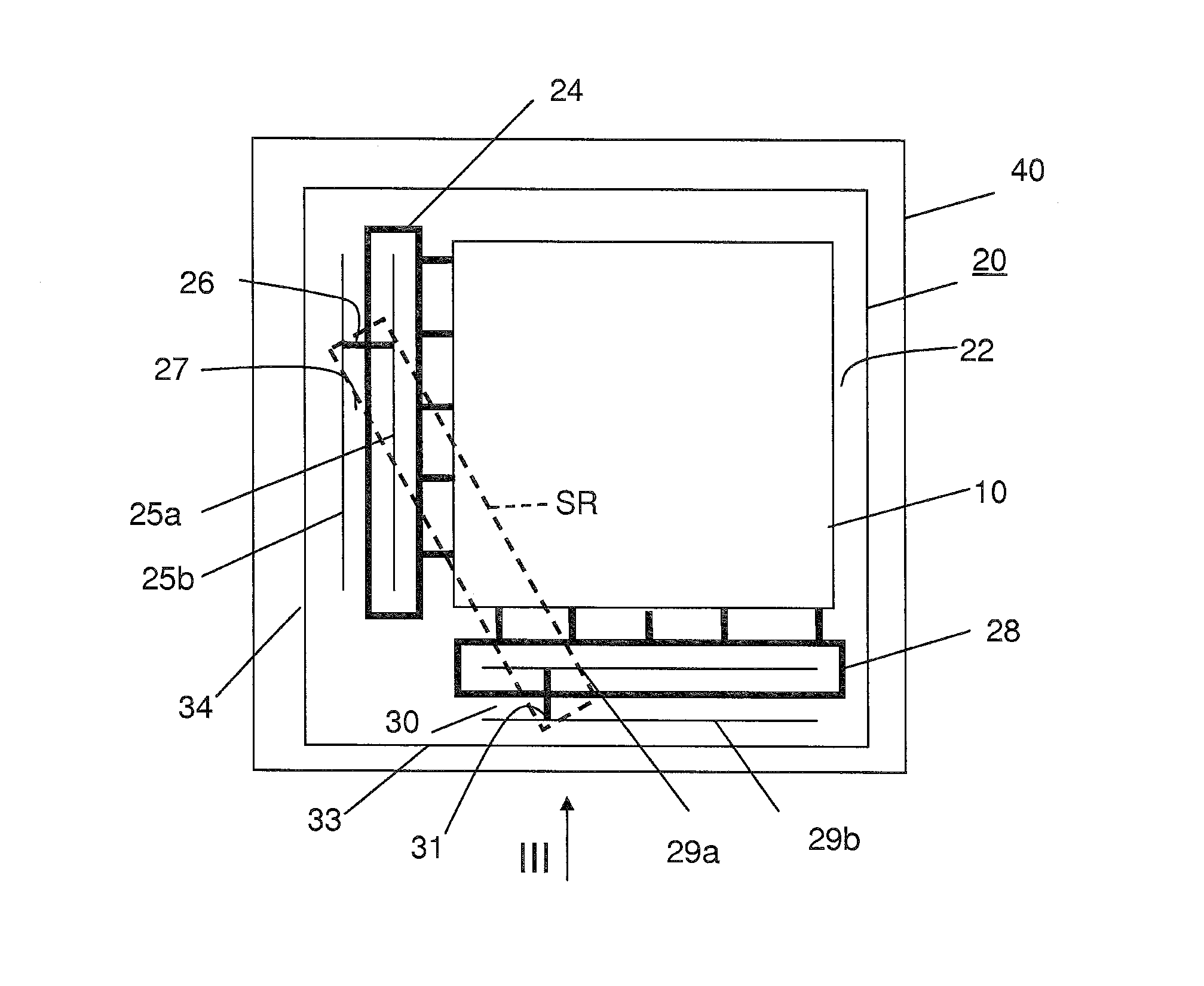
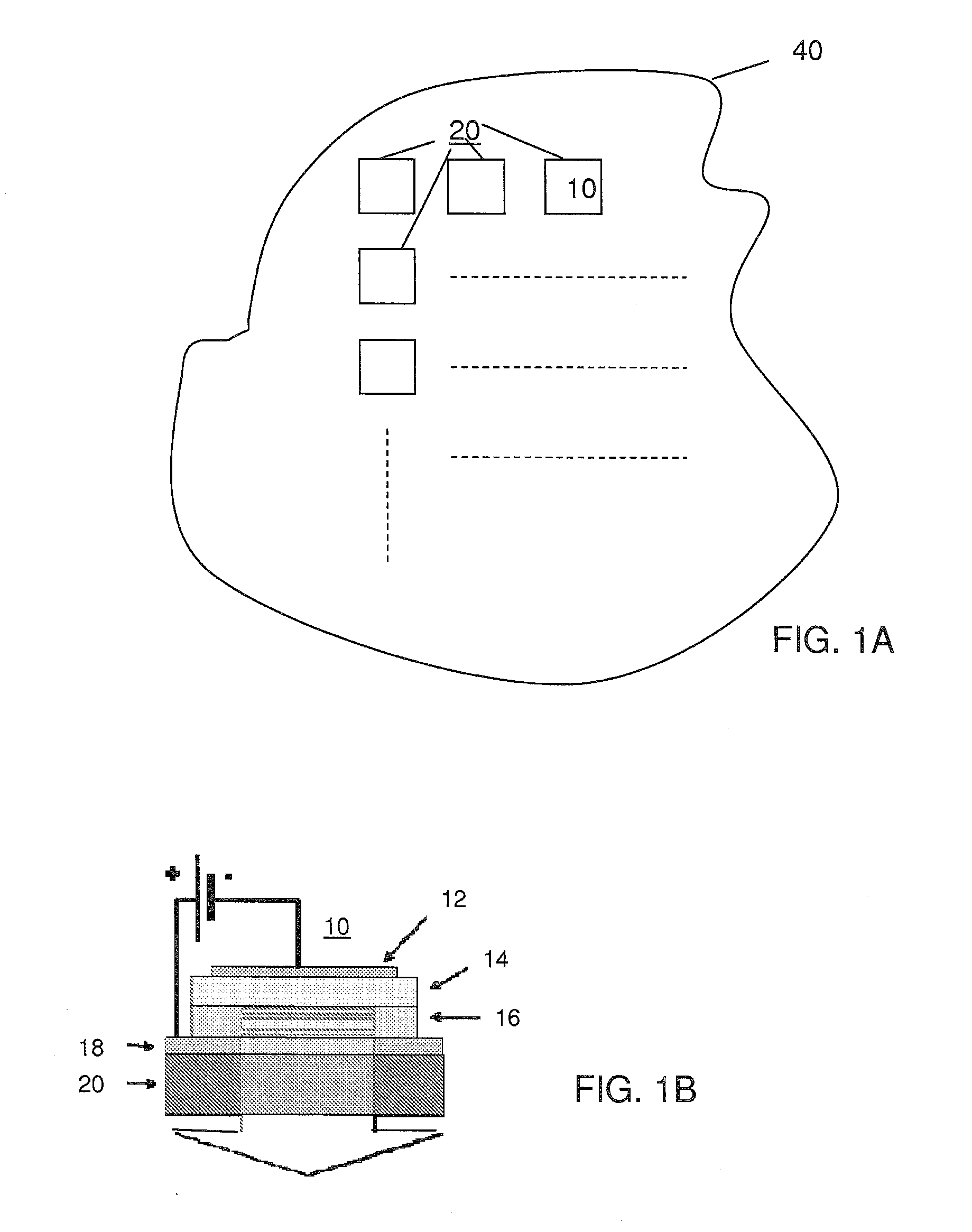
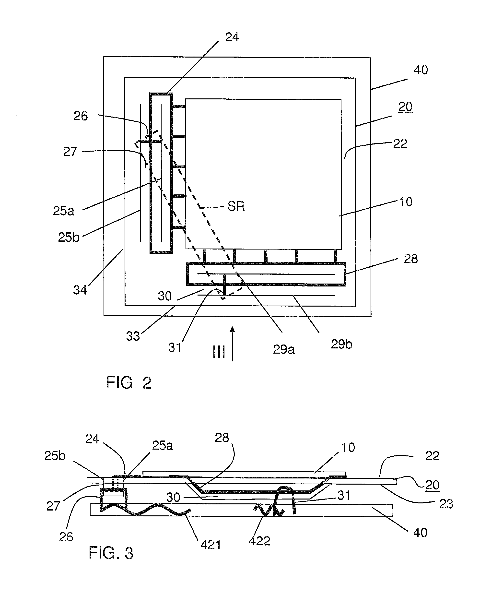
[0056]The invention is described more fully hereinafter with reference to the accompanying drawings, in which embodiments of the invention are shown. This invention may, however, be embodied in many different forms and should not be construed as limited to the embodiments set forth herein. Rather, these embodiments are provided so that this disclosure will be thorough and complete, and will fully convey the scope of the invention to those skilled in the art. In the drawings, the size and relative sizes of layers and regions may be exaggerated for clarity.

[0057]It will be understood that, although the terms first, second, third etc. may be used herein to describe various items these items should not be limited by these terms. Items are understood too mean features described such components or elements or aspects of components or elements, e.g. a surface of an element or a height of an element. These terms are only used to distinguish one item from another item. Thus, a first item cou...


PUM

PropertyMeasurementUnit
Fractionaaaaaaaaaa
Electrical conductivityaaaaaaaaaa
Flexibilityaaaaaaaaaa

Abstract

An assembly is provided of an electro-physical transducer (10) on a flexible foil (20) with a carrier (40). The flexible foil (20) has a first main surface (22) provided with at least a first electrically conductive track (24) connected to the electro-physical transducer and opposite said first main surface a second main surface (23) facing towards the carrier. At least a first incision (25a) extends through the flexible foil alongside said at least a first electrically conductive track, therewith defining a strip shaped portion (27) of the flexible foil that carries a portion of the at least a first electrically conductive track. The at least a first electrically conductive track is electrically connected to an electrical conductor (421) of the carrier, and the flexible foil is attached to the carrier with its strip shaped portion.

Description

BACKGROUND OF THE INVENTION[0001]1. Field of the invention[0002]The present invention relates to an assembly. The present invention further relates to a component for an assembly. The present invention still further relates to a method of manufacturing an assembly.[0003]2. Related Art[0004]An electro-physical transducer is defined herein as a device that converts an electrical signal into a physical phenomenon, or that converts a physical phenomenon into an electrical signal. Examples of the first are electro-luminescent devices, electro-acoustic devices, and electro-chrome devices. Examples of the second are photovoltaic devices, acoustic sensors, and touch sensors.[0005]First stretchable substrate materials are available (e.g. Belgian-funded SWEET project or the EU-funded STELLA project). There is a need to assemble electro-physical transducer devices with such stretchable materials. Usually such elements themselves however are not stretchable. Electro-optical devices are known th...

Claims


Application Information

Patent Timeline
IPC IPC(8): H05K1/02H05B33/10H05B33/08H02S30/20H05B44/00
CPCG09F9/00Y10T29/4913H01L27/3293H01L51/5203H01L2251/5338H01L2251/5361H01R4/04H01R4/70H01R12/7076H05K1/0283H05K1/038H05K1/147H05K1/189H05K3/321H05K3/325H05K3/365H05K2201/029H05K2201/0311H05K2201/046H05K2201/083H05K2201/09081H05K2201/09281H05K2201/10106H05K2201/10287H05K2201/10484H05B33/0896H05B33/10H05K1/0277H05K13/04Y02E10/50H01L31/0392H01L31/042G09F19/22H10K59/18H10K2102/311H05B45/60H10K50/805
Inventor VAN HECK, GERARDUS TITUSDE KOK, MARGARETHA MARIAVAN DEN BRAND, JEROEN
Owner NEDERLANDSE ORG VOOR TOEGEPAST-NATUURWETENSCHAPPELIJK ONDERZOEK (TNO)
Why Eureka
Try Eureka