Video display apparatus

a video display and display technology, applied in the direction of television systems, color television details, casings/cabinets/drawer details, etc., can solve the problems of panel cracking and product strength decline, and achieve the effect of obtaining predetermined strength

Active Publication Date: 2013-08-08
PANASONIC INTELLECTUAL PROPERTY MANAGEMENT CO LTD
View PDF4 Cites 8 Cited by
  • Summary
  • Abstract
  • Description
  • Claims
  • Application Information

AI Technical Summary

Benefits of technology

[0010]Advancing the thinning of the plasma display apparatus in this manner decreases strength of the product, and poses a possibility that a panel crack is caused by drop impact and vibration during transportation, and external force during installation. Countermeasures against the drop impact and the vibration, and the external force are necessary not only in the plasma display apparatus, but also in the case of another flat display type of video display apparatuses.
[0013]According to the present disclosure, there can be provided a plasma display apparatus that can easily obtain predetermined strength, even when the product is made thinner, and in which a panel crack is hardly caused even if the apparatus is subjected to drop impact and vibration, and external force.

Problems solved by technology

Advancing the thinning of the plasma display apparatus in this manner decreases strength of the product, and poses a possibility that a panel crack is caused by drop impact and vibration during transportation, and external force during installation.

Method used


Image

  • Video display apparatus
  • Video display apparatus
  • Video display apparatus

Examples


Embodiment Construction

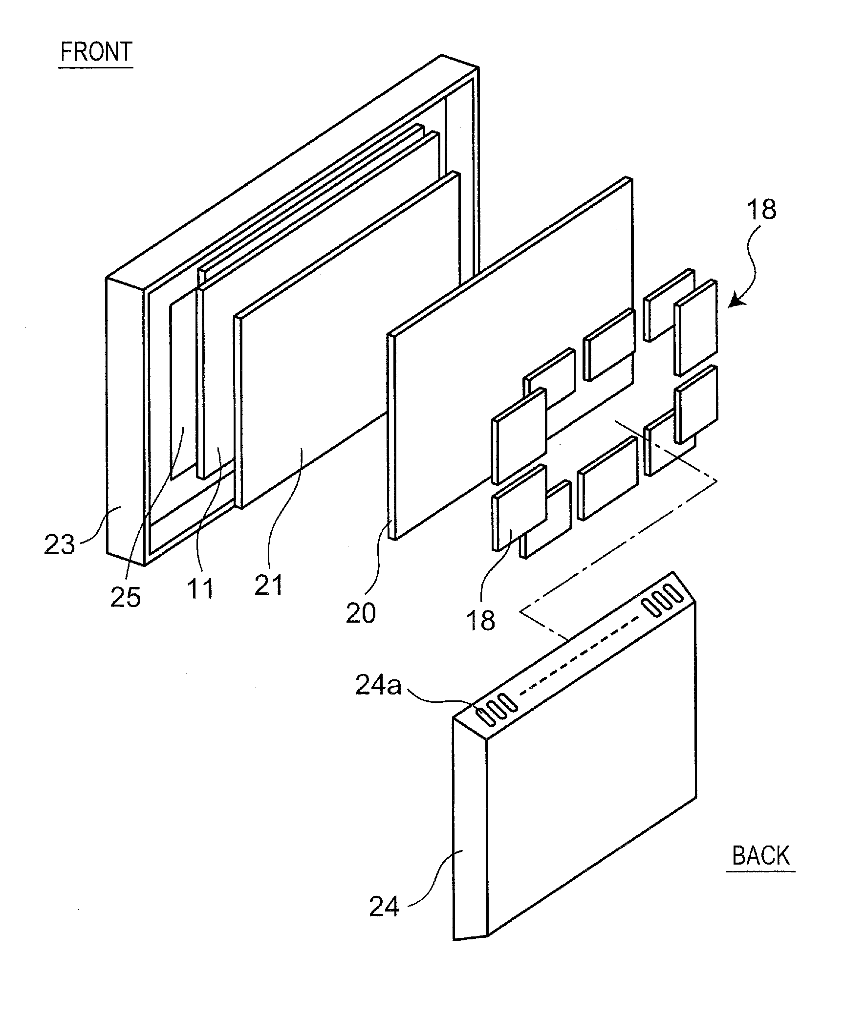
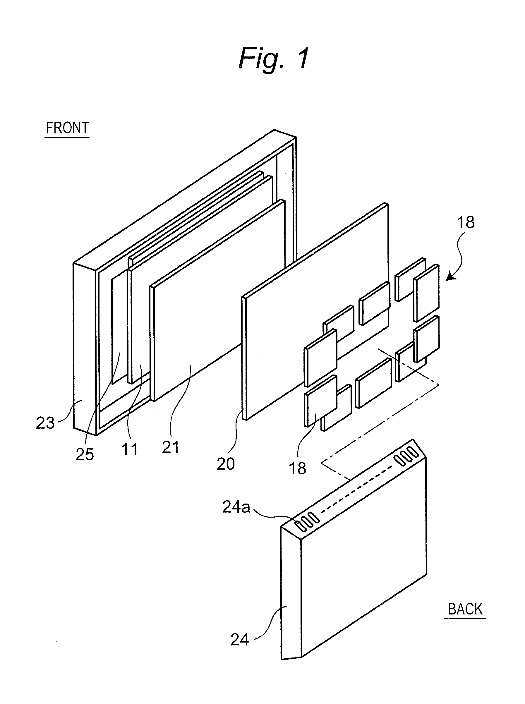
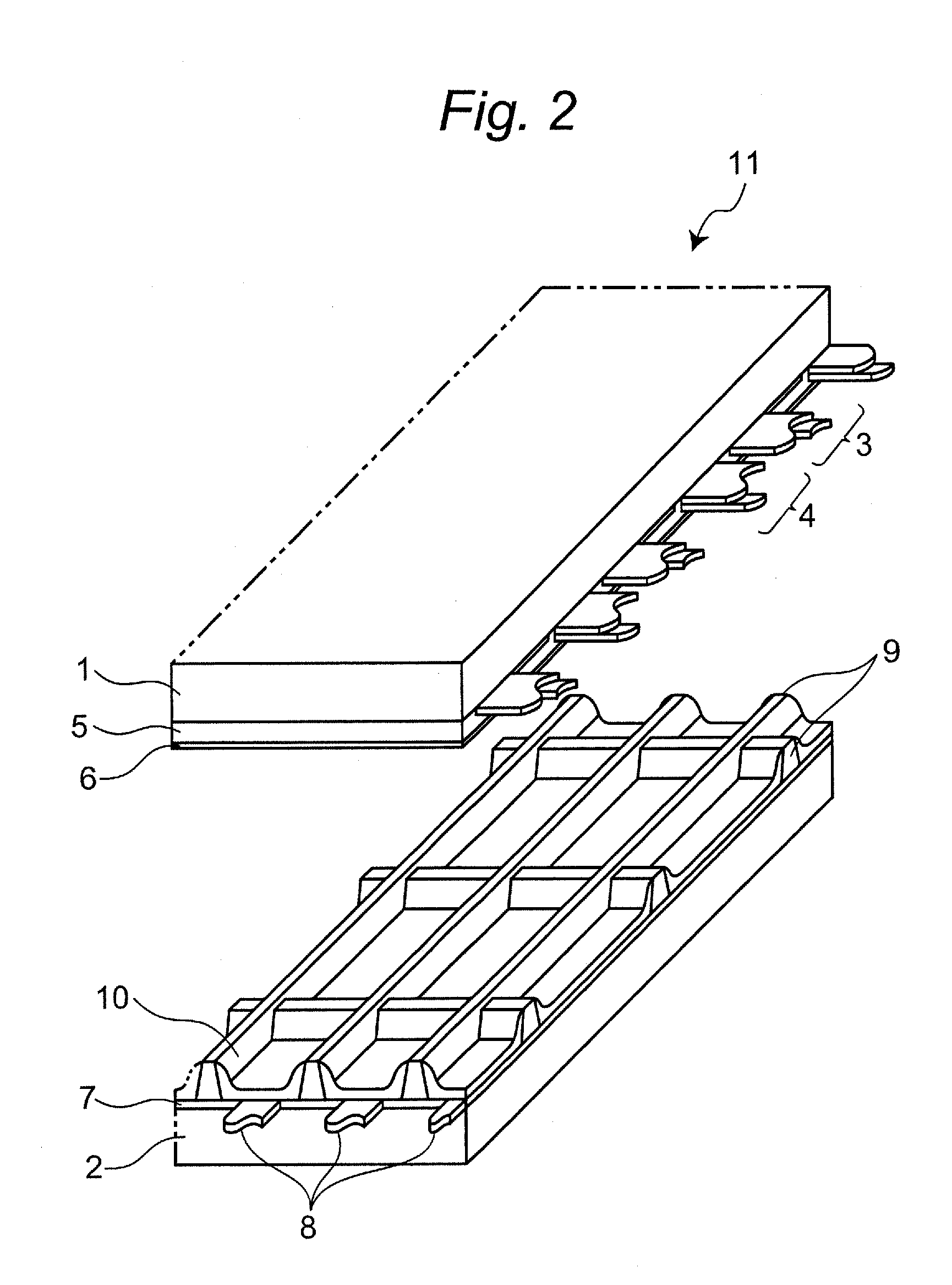
[0026]While a plasma display apparatus according to one embodiment of the present disclosure will be described with reference to FIGS. 1 to 10, aspects for carrying out the present disclosure are not limited thereto. Moreover, meanings of terms regarding positions and directions in the following description are as follows, unless they are particularly mentioned. Referring to FIG. 1, for the terms “front” and “back”, a display panel 11 (hereinafter, simply referred to as a “panel”) is used as a reference. That is, of both surfaces of the panel 11, a side where an image is displayed in an image display area (refer to reference A in FIG. 7) is “front”, and an opposite side thereof is “back”. For “inside” and “outside”, the image display area “A” is used as a reference. That is, a position near a center of the image display area “A” with respect to a specific position is “inside” the specific position. On the contrary, a position far from the center of the image display area “A” with re...


PUM


Abstract

A panel of a plasma display apparatus includes a front substrate and a back substrate arranged in opposition to this front substrate, and an outer circumferential portion of the front substrate and an outer circumferential portion of the back substrate are adhered to each other by a sealing material. The panel is held on a front side of a chassis base portion of a chassis member. A conductive member fixed to an outer circumferential portion of the chassis member includes a first bent portion bent to a back side at a portion located inside a portion where the conductive member is fixed to the chassis member and a first extending portion extending to the back side from the first bent portion. Occurrence of a crack of the panel due to drop impact, vibration, and external force can be prevented.

Description

CROSS-REFERENCE TO RELATED APPLICATIONS[0001]This is a continuation application of International Application No. PCT / JP2012 / 000171, with an international filing date of Jan. 13, 2012, which claims priority of Japanese Patent Application No.: 2011-005806 filed on Jan. 14, 2011, the content of which is incorporated herein by reference.BACKGROUND[0002]1. Technical Field[0003]The technical field relates to a flat panel display type of video display apparatus such as a plasma display apparatus in which a plasma display panel (hereinafter, referred to as a panel) is used as a display device.[0004]2. Description of Related Art[0005]A panel used in this plasma display apparatus is roughly divided into an AC type and a DC type in terms of driving, and divided into two types of a surface discharge type and a facing discharge type in terms of discharge form. In terms of increase in definition and screen size, and ease of manufacturing, currently, a mainstream of the plasma display apparatus is...

Claims


Application Information

Patent Timeline
Patent Type & Authority Applications(United States)
IPC IPC(8): H04N5/64
CPCH05K5/02H04N5/64H05K9/0054
Inventor NAKASE, KIYOTAKA
Owner PANASONIC INTELLECTUAL PROPERTY MANAGEMENT CO LTD
Why Eureka
Try Eureka