Illumination device and luminaire

a technology of illumination device and luminaire, which is applied in the direction of fixed installation, lighting and heating apparatus, light source combination, etc., can solve the problems of relatively expensive, laborious mounting, and relatively large construction of known luminaires, and achieves the disadvantages of being relatively bulky, relatively expensive, and relatively complicated

Active Publication Date: 2013-08-08
SIGNIFY HLDG BV
View PDF14 Cites 125 Cited by
  • Summary
  • Abstract
  • Description
  • Claims
  • Application Information

AI Technical Summary

Benefits of technology

[0007]Preferably, the reflector is diffusely reflective or has at least a highly diffusive reflection component, for example in that the reflector is more than 70% or 80% or preferably 95% or more diffusely reflective and / or less than 30% or 20% or 5% or even less specularly reflective. Diffuse reflectors allow porous, open, or rough structures which are better suited for the absorption of sound than closed, smooth surfaces which are better suited for use as specularly reflective surfaces. Furthermore, diffusely reflective surfaces reduce the risk of glare, which is of particular importance in office lighting and for working with computers, and diffusely reflective surfaces are particularly suitable in environments where accurate beams, such as required for spotlighting, are somewhat less critical. Yet, if specularly reflective surfaces are desired, the acoustically absorbing material can be coated with a reflective metal coating, for example an aluminum coating. For a semi-specularly reflective reflector, a coating of satinized, white paint on the sound-absorbing material is appropriate.
[0028]In an embodiment, the luminaire comprises the first illumination device with a first reflector for providing a first beam, characterized in that the luminaire comprises integral with the first illumination device at least one further illumination device with at least one further reflector for providing at least one further beam, the further illumination device forming a further one of said concave surface elements. Said first beam and said further beam could substantially have the same shape and / or direction, but alternatively could be significantly different with respect to these characteristics. Hence, an advantageous luminaire is obtained for which desired predetermined light characteristics can be selected relatively easily. Such an illumination system provides a very interesting design feature which may be used to achieve a specific required illumination distribution and aesthetics.

Problems solved by technology

This causes the known luminaire to have the disadvantages of being relatively expensive, involving laborious mounting, and having a relatively complicated and rather bulky construction.

Method used


Image

  • Illumination device and luminaire
  • Illumination device and luminaire
  • Illumination device and luminaire

Examples


first embodiment

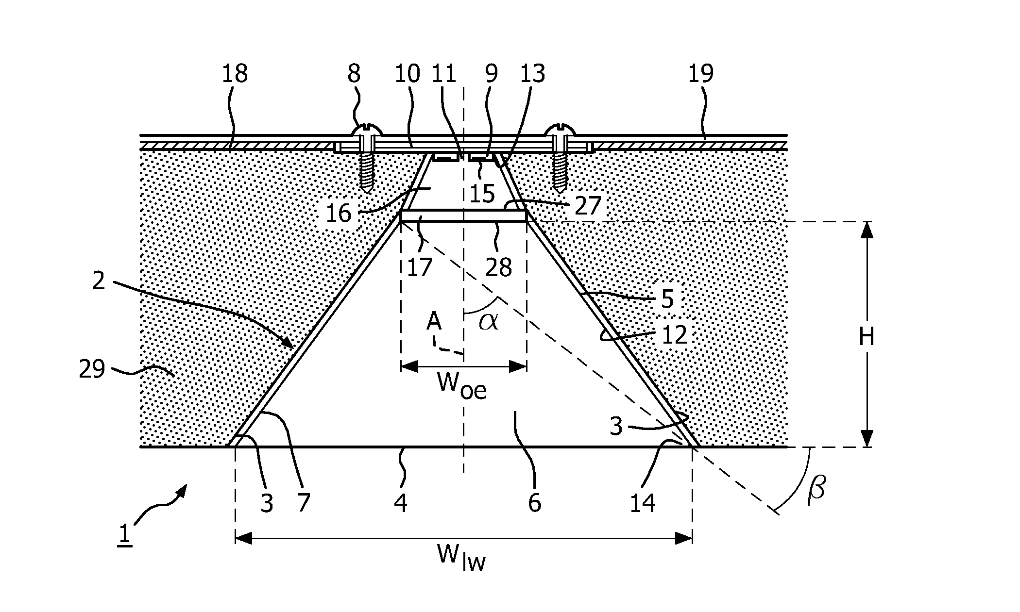
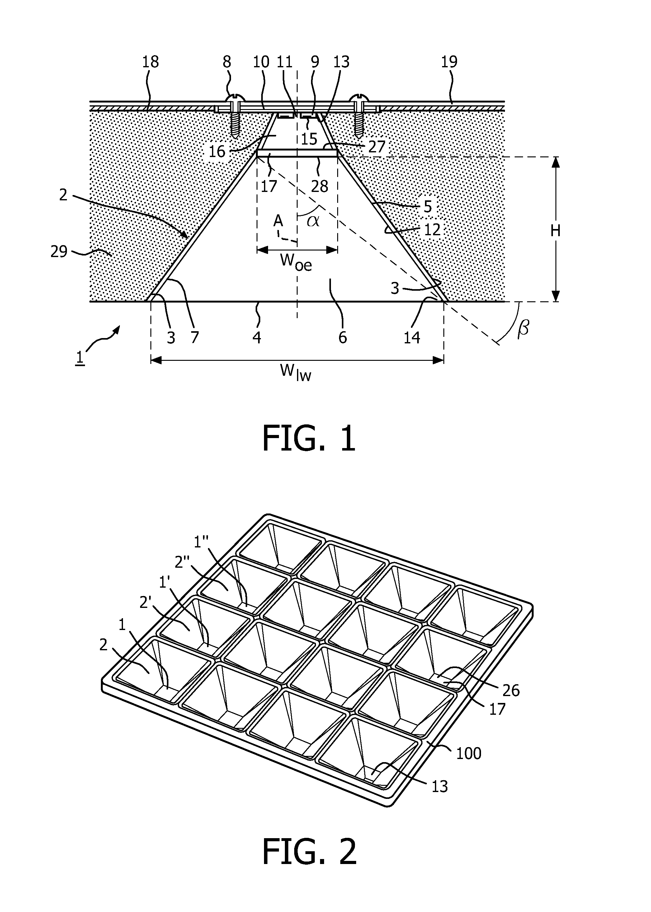
[0037]FIG. 1 shows a cross section of the illumination device 1 according to the invention. The illumination device comprises a concave reflector 2 which borders, with an outer edge 3, on a light emission window 4, the reflector and light emission window constituting a boundary 5 of a reflector cavity 6. The reflector has a reflective surface 7 facing the light emission window. The illumination device further comprises lamp holding means 8 accommodating a light source 9; in FIG. 1 a plurality of white, red, green and blue (WRGB) light emitting LEDs are mounted on a PCB 10 with a light reflective surface 11. In this embodiment, the RGB LEDs do not render the right color for general illumination, but are added to the white LEDs to tune the color. Said PCB and LEDs together are provided in the reflector cavity, i.e. in this particular case form part of the boundary of the reflector cavity. The reflector is acoustically absorbing, diffusely reflective and flame resistant and heat resist...

second embodiment

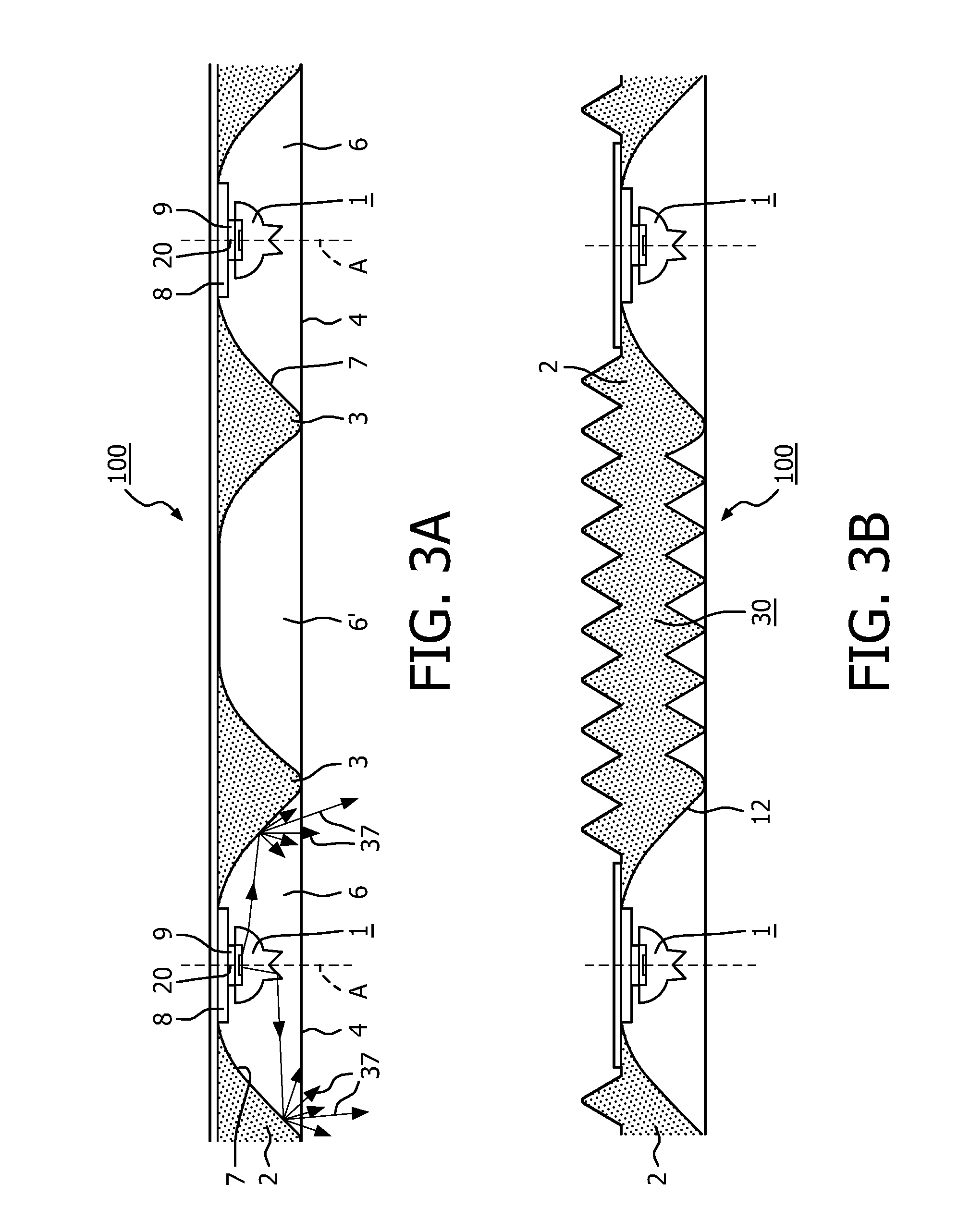
[0040]FIG. 3A shows a cross section of a luminaire 100 with a plurality of illumination devices 1 according to the invention. Illumination device 1 is a luminaire with a round, cup shaped reflector 2 in one piece, which reflector borders, with an outer edge 3, on a round light emission window 4, the reflector and the light emission window constituting a boundary of a reflector cavity 6 . The round reflector has a center 20 through which an axis A extends that coincides with an optical axis of the luminaire and extends transversely to the light emission window. In the center a light source 9 is provided on lamp holding means 8, i.e. a single side-emitting white LED mounted on a PCB, but this could alternatively be a halogen incandescent lamp provided with a mirroring coating on a side of its bulb surface facing towards the light emission window. Said LED issues light in a direction transverse to the axis towards the essentially diffusely reflective surface 7 of the round reflector; “...

third embodiment

[0041]FIG. 3B shows a cross section of a luminaire 100 comprising a plurality of illumination devices 1 according to the invention, which is analogous to the luminaire of FIG. 3A, but in which the reflector cavity 6 without light source (see FIG. 3A) is substituted by a wave-shaped sound absorbing and light reflective mass 30 having a saw tooth structure when viewed in cross section. Said reflective mass preferably is of the same material as the material used for the edge wall 12 of the reflector 2.

[0042]FIG. 4A shows a second embodiment of the illumination device according to the invention. The illumination device has a reflector 2 composed of two reflector parts 2a, 2b, i.e. two mirror-positioned elongated concave reflectors parts 2a, 2b, with undulated surfaces and which are mounted on a centrally positioned, elongated housing 18. The reflector has an outer edge 3 that borders on a light emission window 4. The reflector and the light emission window together constitute a boundary...


PUM

PropertyMeasurementUnit
temperatureaaaaaaaaaa
reflectivityaaaaaaaaaa

Abstract

Today the use of false ceilings is decreasing as it involves too high an energy consumption. The tendency nowadays is to have bare concrete ceilings onto which luminaires are mounted, which often causes acoustical problems. The invention deals with these acoustical problems and relates to an illumination device (1) comprising a concave reflector (2) bordering,with an outer edge (3),on a light emission window (4). The reflector has a reflective surface (7) facing the light emission window. The illumination device further comprises lamp holding means (8) for accommodating a light source (9),and said lamp holding means being positioned in between the reflective surface and the light emission window. The illumination device is characterized in that the reflector is made of acoustically absorbing material.

Description

FIELD OF THE INVENTION[0001]The invention relates to an illumination device comprising:[0002]a concave reflector bordering, with an outer edge, on a light emission window, the reflector and the light emission window constituting a boundary of a reflector cavity, and the reflector having a reflective surface facing the light emission window;[0003]lamp holding means for accommodating a light source and being provided at or within the boundary of the reflector cavity.[0004]The invention further relates to a luminaire comprising at least one illumination device according to the invention.BACKGROUND OF THE INVENTION[0005]Such an illumination device is known from U.S. Pat. No. 5,782,551. The known illumination device is a luminaire that is mounted with a backside to a deck. An acoustical shell, which acts as a reflector and which can produce an office light beam with conventional louver optics, is provided at the backside of the luminaire. Said acoustical shell is made such that it allows...

Claims


Application Information

Patent Timeline
Patent Type & Authority Applications(United States)
IPC IPC(8): F21V7/22
CPCE04B9/0464E04B9/34F21S8/04F21V5/002F21V7/005F21V7/0083F21S8/061F21V9/16F21V33/006F21Y2101/02F21Y2103/003F21Y2113/005F21V7/22F21S2/00F21V7/0041F21V9/06F21V9/08F21V13/14F21Y2103/10F21Y2113/13F21Y2115/10F21V1/17F21V3/08F21V3/12F21V5/10F21V7/26F21V7/30F21V9/30F21V9/45
Inventor VISSENBERG, MICHEL CORNELIS JOSEPHUS MARIEDINGEMANS, ANTONIUS PETRUS MARINUSVAN BOMMEL, MARCUS JOZEFBOONEKAMP, ERIK PAUL
Owner SIGNIFY HLDG BV
Why Eureka
Try Eureka