Relay station for relaying communication between user apparatus and base station, and relay method

Active Publication Date: 2013-08-08
NTT DOCOMO INC
View PDF1 Cites 9 Cited by
  • Summary
  • Abstract
  • Description
  • Claims
  • Application Information

AI Technical Summary

Benefits of technology

The patent aims to solve the problem of different parameters between a user device and a relay station, as well as between the relay station and the base station. This can occur due to different protocol stacks used for communication. The invention ensures that the user device, relay station, and base station can communicate properly through a relay station, regardless of the parameter settings. Additionally, the invention identifies when the relay station is transferring a signal or generating and transmitting a signal to ensure proper service quality.

Problems solved by technology

However, at least at the time of filing of this application, it is not reported how to match parameters used for communication in each of the Uu side and the Un side.
Also, it is not clear how the service quality is ensured in a case where the relay station transfers a packet and in a case where the relay station generates and transmits a packet.

Method used


Image

  • Relay station for relaying communication between user apparatus and base station, and relay method
  • Relay station for relaying communication between user apparatus and base station, and relay method
  • Relay station for relaying communication between user apparatus and base station, and relay method

Examples


embodiment 1

1. System

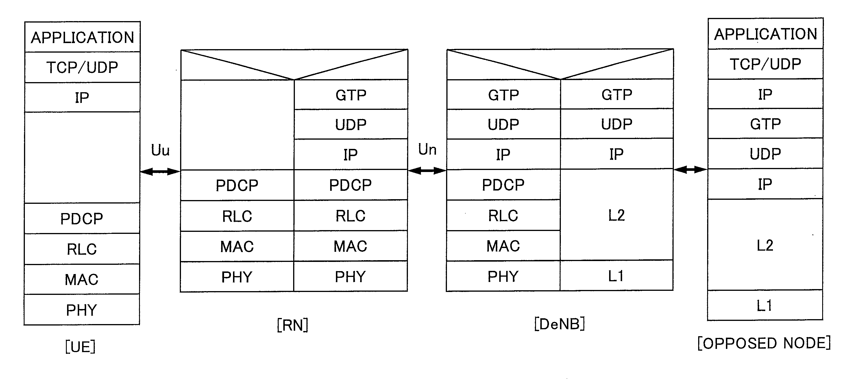
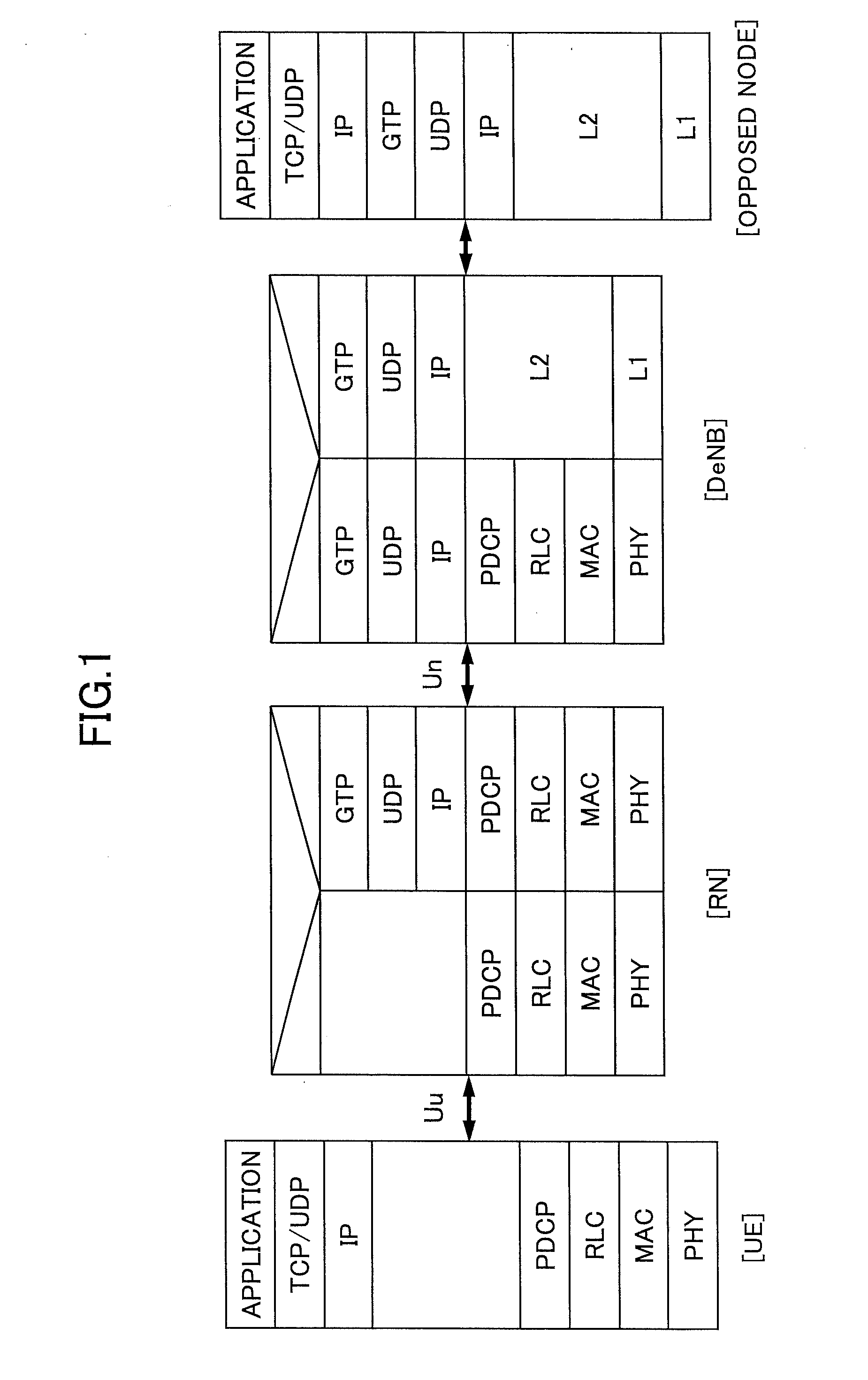
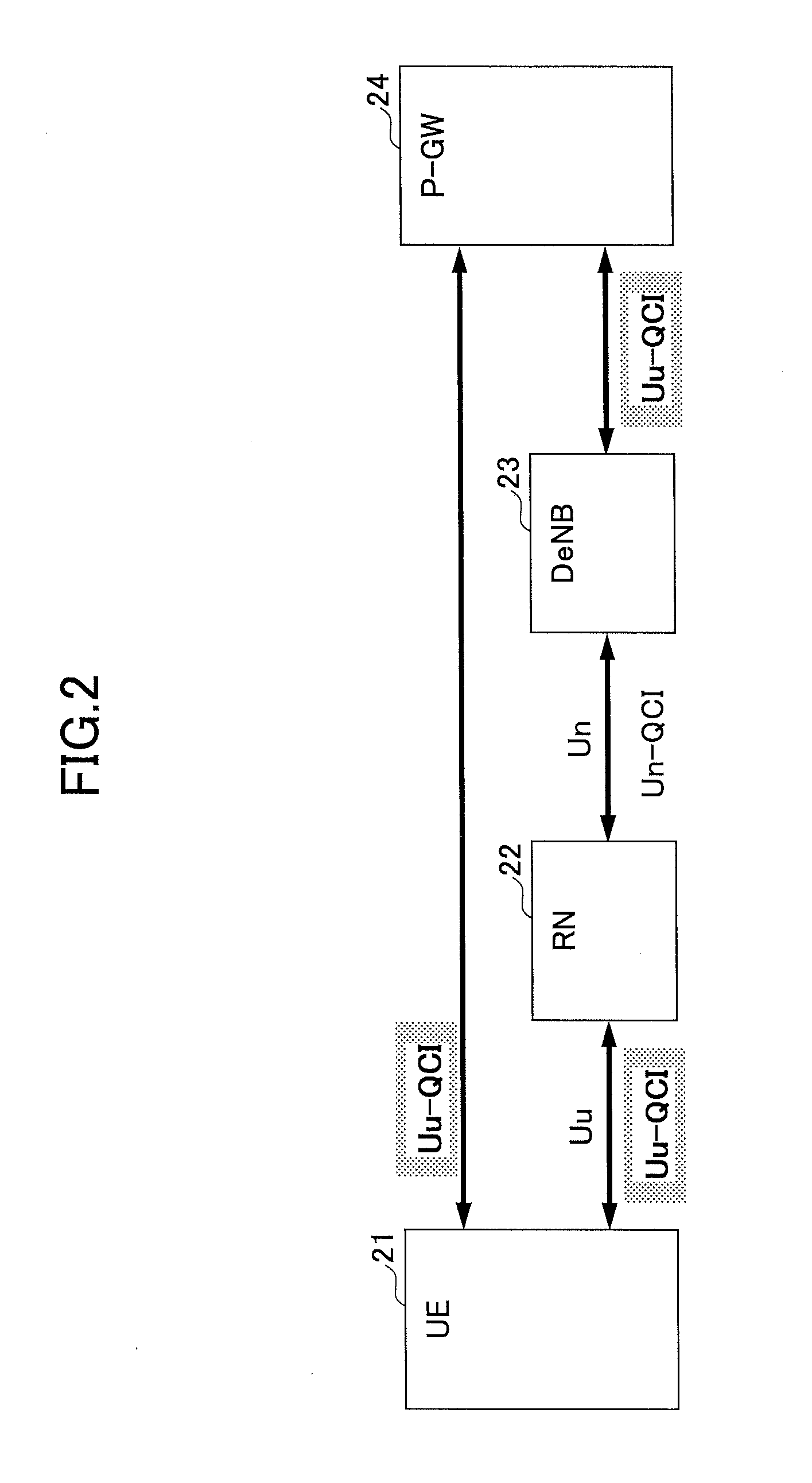
[0043]FIG. 2 shows a schematic block diagram of the communication system according to an embodiment of the present invention. FIG. 2 shows a user apparatus (UE) 21, a relay station (RN) 22, a base station (DeNB) 23 and a packet data network gateway (P-GW) 24. As mentioned above, the radio interface between the user apparatus (UE) 21 and the relay station (RN) 22 is referred to as “Uu”. The radio interface between the relay station (RN) 22 and the base station (eNB) 23 is referred to as “Un”. The user apparatus (UE) may be any proper apparatus that can be used by a user for radio communication. The base station (DeNB) manages radio resources in addition to relaying communication between a user apparatus (UE) in a cell and an upper apparatus such as the packet data network gateway (P-GW). The relay station (RN) relays communication between the user apparatus (UE) and the base station (DeNB). The packet data network gateway (P-GW) has a connection function between a mobile co...

first modified example

4. First Modified Example

[0068]The QoS class identifier (QCI) can be set for packets in various methods. For example, QCI may be derived from one or more flow identifiers included in the packet. The flow identifier indicates, for example, a source address (IP address, for example), a destination address (IP address, for example), a port number used for communication, a protocol type used for communication (TCP, for example), DSCP (Diffserv Code Point) value and the like. For example, a predetermined DSCP value or a DSCP value within a predetermined numerical range may be associated with a QCI. As an example, a DSCP value within a range from 23 to 30 is associated with QCI=32. Or, a predetermined destination address may be associated with a predetermined QCI. Further, a combination of a source and a destination may be associated with a QCI. The above-mentioned flow identifier is normally used for filtering (selecting) packets by a Traffic Flow Template (TFT) scheme. In addition, a ne...

second modified example

5. Second Modified Example

[0069]In explanation on FIGS. 3A and 4, a packet generated by the user apparatus (UE) is transmitted to the base station (DeNB) via the relay station (RN) in uplink. The concept of the embodiment can be applied not only to uplink but also to downlink. In this case, although a functional block diagram of the relay station (RN) is similar to one shown in FIG. 4, the packet receiving unit 46 receives a packet from the base station (DeNB), and the packet transmission unit 49 transmits a packet to the user apparatus (UE).

[0070]FIG. 5 shows a flowchart of an operation example in the first modified example, which indicates an operation example of the relay station (RN) in the downlink.

[0071]In step S51, the relay station (RN) receives a packet from the base station (DeNB) via the radio interface (Un).

[0072]In step S52, the relay station (RN) analyzes the received packet, and identifies a QoS class identifier (Un−QCI) set for the radio interface (Uu). The QoS class...


PUM


Abstract

A relay station includes a signal generation unit configured to generate a signal in the relay station and a receiving unit configured to receive a signal from a first communication station. The relay station further includes a signal generating node identifying unit configured to identify whether a signal to be transmitted to a second communication station is a received signal received from the first communication station or a generated signal generated by the signal generation unit. The relay station further includes a signal transmission unit configured to transmit both or one of the received signal and the generated signal associated with a radio bearer to the second communication station.

Description

RELATED APPLICATIONS[0001]This application is a National State application of International Patent Application No. PCT / JP2011 / 072107, filed on Sep. 27, 2011, which claims priority pursuant to 35 U.S.C. §119(a) to Japanese patent application No. 2010-226799, filed on Oct. 6, 2010. Both Japanese patent application No. 2010-226799 and International Patent Application No. PCT / JP2011 / 072107 are hereby incorporated by reference in their entirety.BACKGROUND OF THE INVENTION[0002]1. Technical Field[0003]One or more embodiments of the present invention relate to a relay station and a relay method for relaying communication between a user apparatus and a base station[0004]2. Background Art[0005]In a cellular mobile communication system, in order to enlarge coverage of a cell and / or in order to realize load distribution in a base station (eNB), there is a case where a relay station (relay node: RN) is provided between the base station (eNB) and a user apparatus (UE). The base station (eNB) in ...

Claims


Application Information

Patent Timeline
IPC IPC(8): H04W88/04
CPCH04B7/15528H04B7/15507H04W84/047H04W28/18H04W88/04H04W16/26H04W72/04
Inventor MORIOKA, YASUFUMIYAMADA, AKIRATAKAHASHI, HIDEAKIIWAMURA, MIKIOHAGIWARA, JUNICHIRO
Owner NTT DOCOMO INC
Why Eureka
Try Eureka