Chain

a technology of chain and pin, applied in the field of chains, can solve the problems of increasing wear loss of the chain, elongation of the chain, and insufficient lubrication of the connecting pin and the pin hole, so as to reduce friction, improve the holdability of the back surface of the link plate in the guide rows, and suppress wear.

Active Publication Date: 2013-08-08
TSUBAKIMOTO CHAIN CO
View PDF11 Cites 6 Cited by
  • Summary
  • Abstract
  • Description
  • Claims
  • Application Information

AI Technical Summary

Benefits of technology

[0020]With this arrangement as in the previously described arrangement, oil holdability on the back surfaces of the link plates in the guide rows is improved, friction is reduced, and wear is suppressed. Frictional losses are also reduced because the link plates of the non-guide rows do not contact the chain guide and the contact area between the silent chain and the chain guide is thereby reduced.
[0021]Accordi

Problems solved by technology

In such a chain, the area of contact between the back surface 514 and the chain guide increases over time, and wear loss of the chain increases.
Thus lubrication of the connecting pins and the pin holes becomes inadequate, and excessive wear between the pins and the inner surfaces 515 of the pin holes can result in el

Method used


Image

  • Chain
  • Chain
  • Chain

Examples


Embodiment Construction

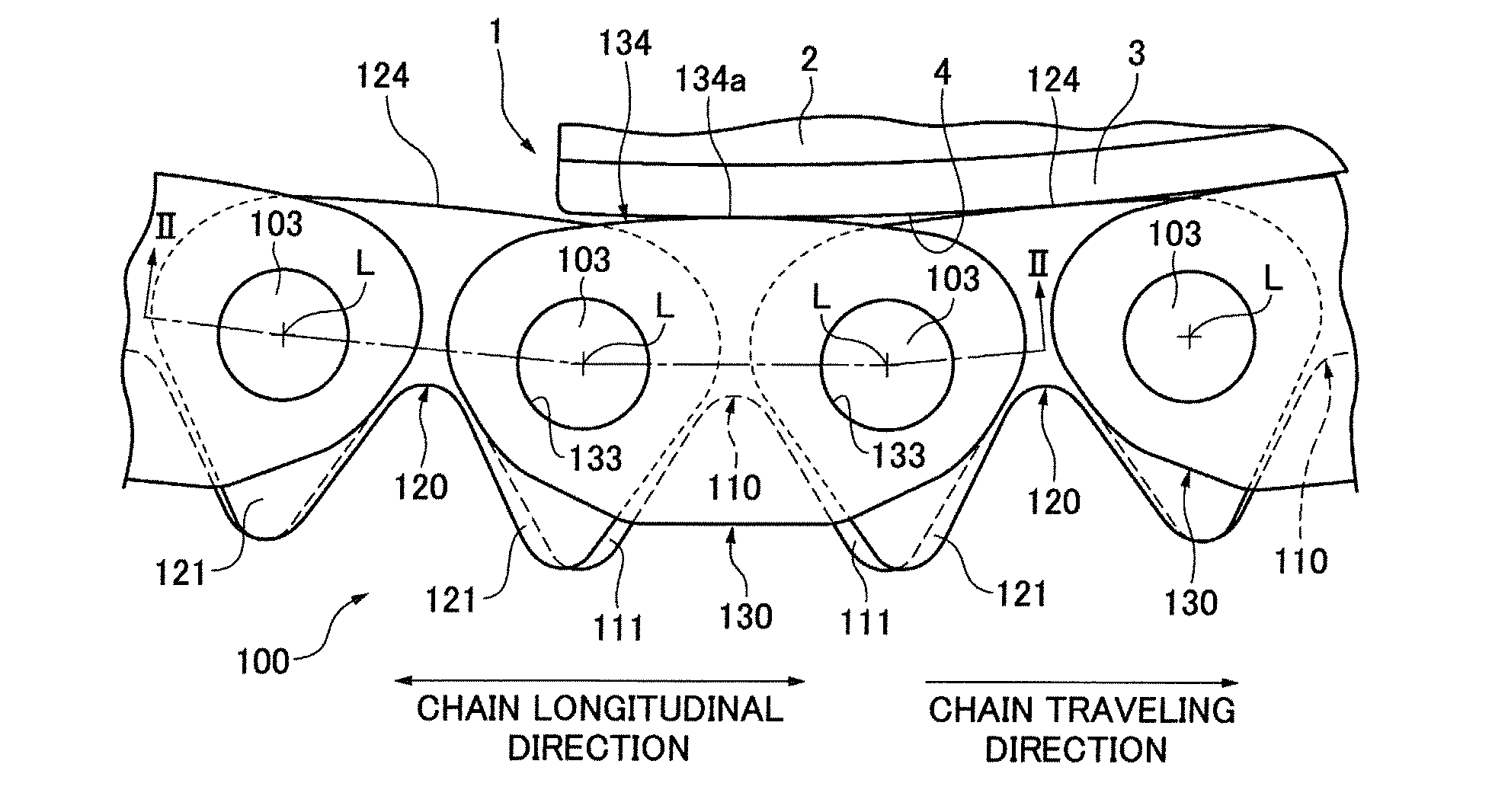
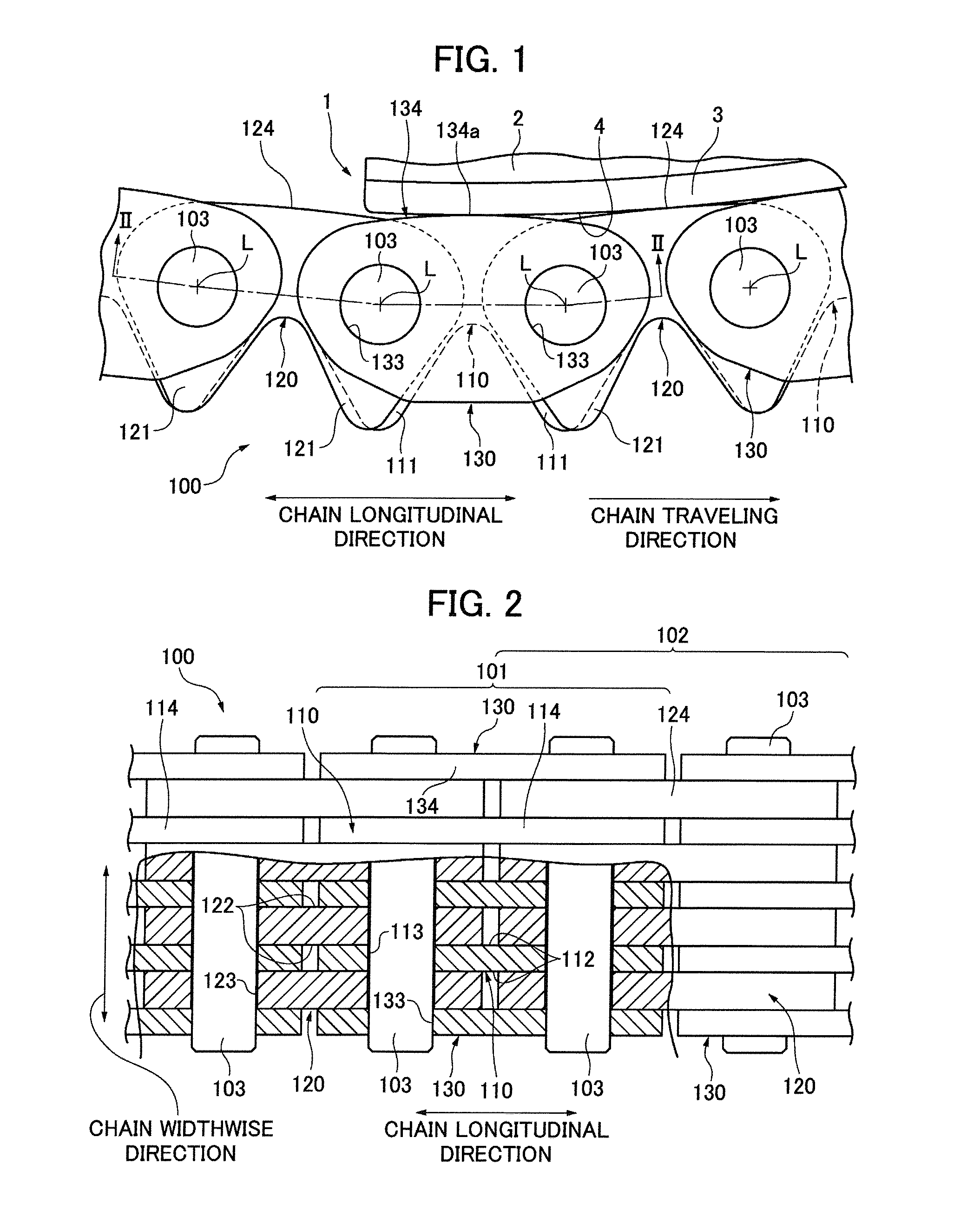
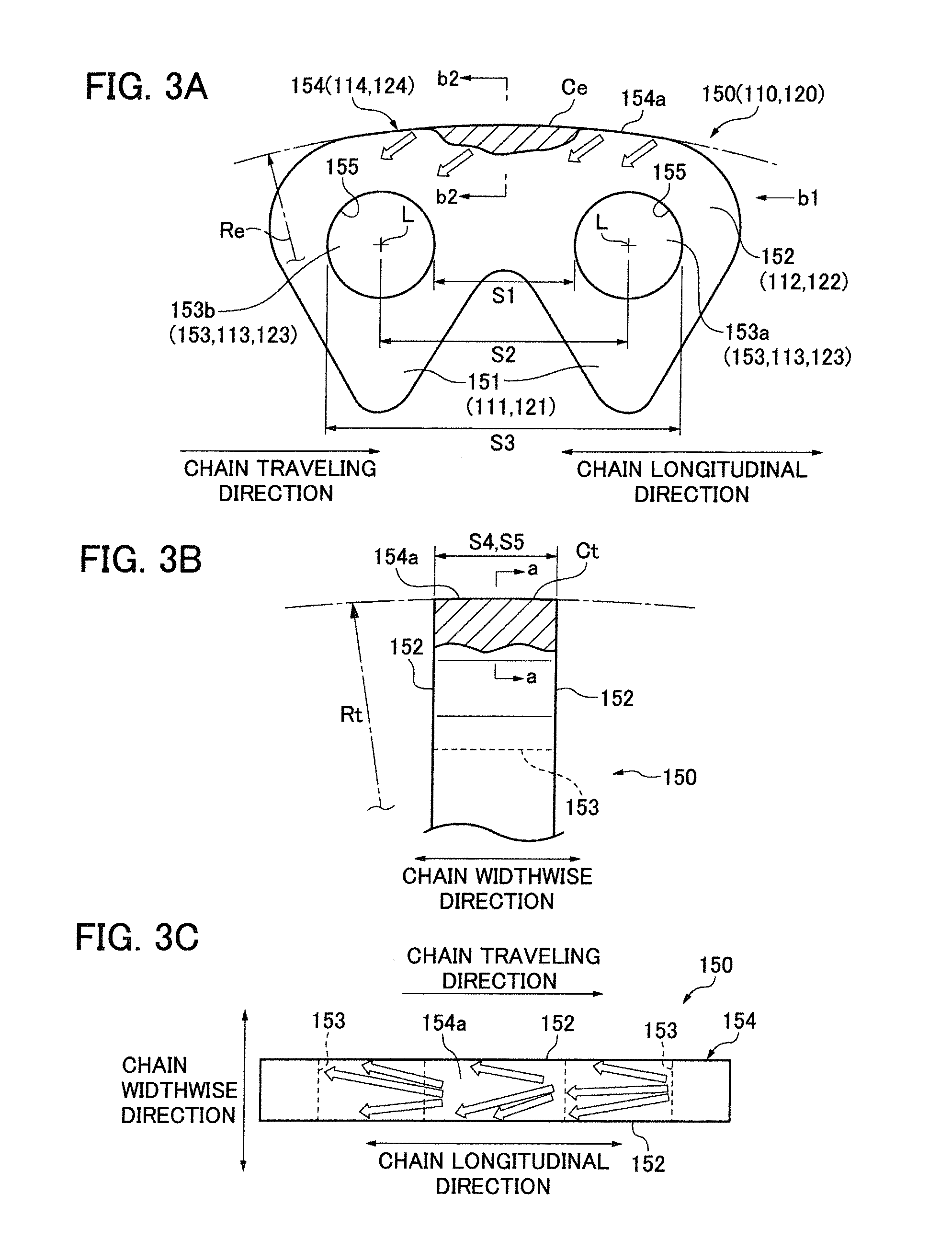
[0029]The chain 100 depicted FIGS. 1, 2 and 3A through 3C is an endless transmission chain used to transmit power from a driving sprocket to one or more driven sprockets in a machine. A typical application for such a chain is the transmission of power from the crankshaft to one or more camshafts in the timing drive of an automobile engine.

[0030]A chain transmission may include one or more chain guides arranged for sliding engagement with a back of the chain, for guiding the chain as it travels from one sprocket to another. A part of such a guide is shown as guide 1 in FIG. 1.

[0031]The chain guide 1 may be a stationary guide, or movable guide that is biased against the chain by a chain tensioner. The chain guide 1 is composed of a base 2 and a shoe 3 supported by the base 2 and having a surface 4 on which the chain 100 slides.

[0032]The shoe 3 is formed of a wear-resistant synthetic resin or other material that exhibits good wear resistance. The surface 4 of the shoe typically an elon...


PUM


Abstract

In a transmission chain including alternately interleaved and articulably connected sets of link plates, the link plates of least one of the sets have back surfaces arranged for sliding contact with a chain guide. These back surfaces have a convex, substantially arc-shaped, curvature in the longitudinal direction of the chain, and a convex, substantially arc-shaped, curvature in the widthwise direction. The radius of curvature of the widthwise curve of the back surface of each of the link plates of the at least one set is at least as great as the radius of curvature of the curve of the same link plate in the longitudinal direction.

Description

CROSS REFERENCE TO RELATED APPLICATION[0001]The disclosure of Japanese Patent Application No. 2012-022253, filed on Feb. 3, 2012 is incorporated by reference.FIELD OF THE INVENTION[0002]This invention relates to a chain comprising a plurality of first links and a plurality of second links, each link being composed of one or more link plates. The first and second links are arranged alternately along the length of the chain, with the plate or plates of each of the first links interleaved with, i.e., extending in overlapping relationship between, plates of two adjacent second links, and connected articulably by connecting pins extending through pin holes of the link plates. The link plates may be formed with teeth for engagement with sprocket teeth, and have backs for sliding engagement with chain guides.[0003]The chain can be a silent chain of the kind used industrial machinery or in an automobile engine. However, advantages of the invention can be realized in other kinds of transmiss...

Claims


Application Information

Patent Timeline
IPC IPC(8): F16G13/04
CPCF16G13/04F16G13/08F16G13/06B25J19/00H02G11/00
Inventor MIYANAGA, SYOTA
Owner TSUBAKIMOTO CHAIN CO
Why Eureka
Try Eureka