
Gas turbine engine with separate core and propulsion unit

Active Publication Date: 2013-08-15
RAYTHEON TECH CORP
View PDF7 Cites 22 Cited by
  • Summary
  • Abstract
  • Description
  • Claims
  • Application Information

AI Technical Summary

Benefits of technology

The patent describes a gas turbine engine with a unique mounting system for the fan and core engine. The core engine includes a compressor, combustion section, and turbine, which are connected to the fan through a free turbine. The engine is designed to deliver air to the fan in a way that maximizes efficiency and reduces weight. The angle between the two main axes of the engine is defined, and a gear reduction is used between the free turbine and fan. The engine can be mounted to an aircraft wing using a pylon, and there are struts that connect the pylon to the engine. The technical effects of the patent include improved efficiency, reduced weight, and improved mounting system for the fan and core engine.

Problems solved by technology

It has typically not been possible to service any portion of the engine, without removing the concentrically rotating turbines, compressors and fan as a combined unit.
Another challenge with mounting gas turbine engines relates to the so called “disk burst zone.” This zone is an area where broken pieces from a core engine could be driven.
There is a limitation on the mounting of current gas turbine engines in that the disk burst zone cannot extend through the fuel tank.

Method used


Image

  • Gas turbine engine with separate core and propulsion unit
  • Gas turbine engine with separate core and propulsion unit
  • Gas turbine engine with separate core and propulsion unit

Examples


Embodiment Construction

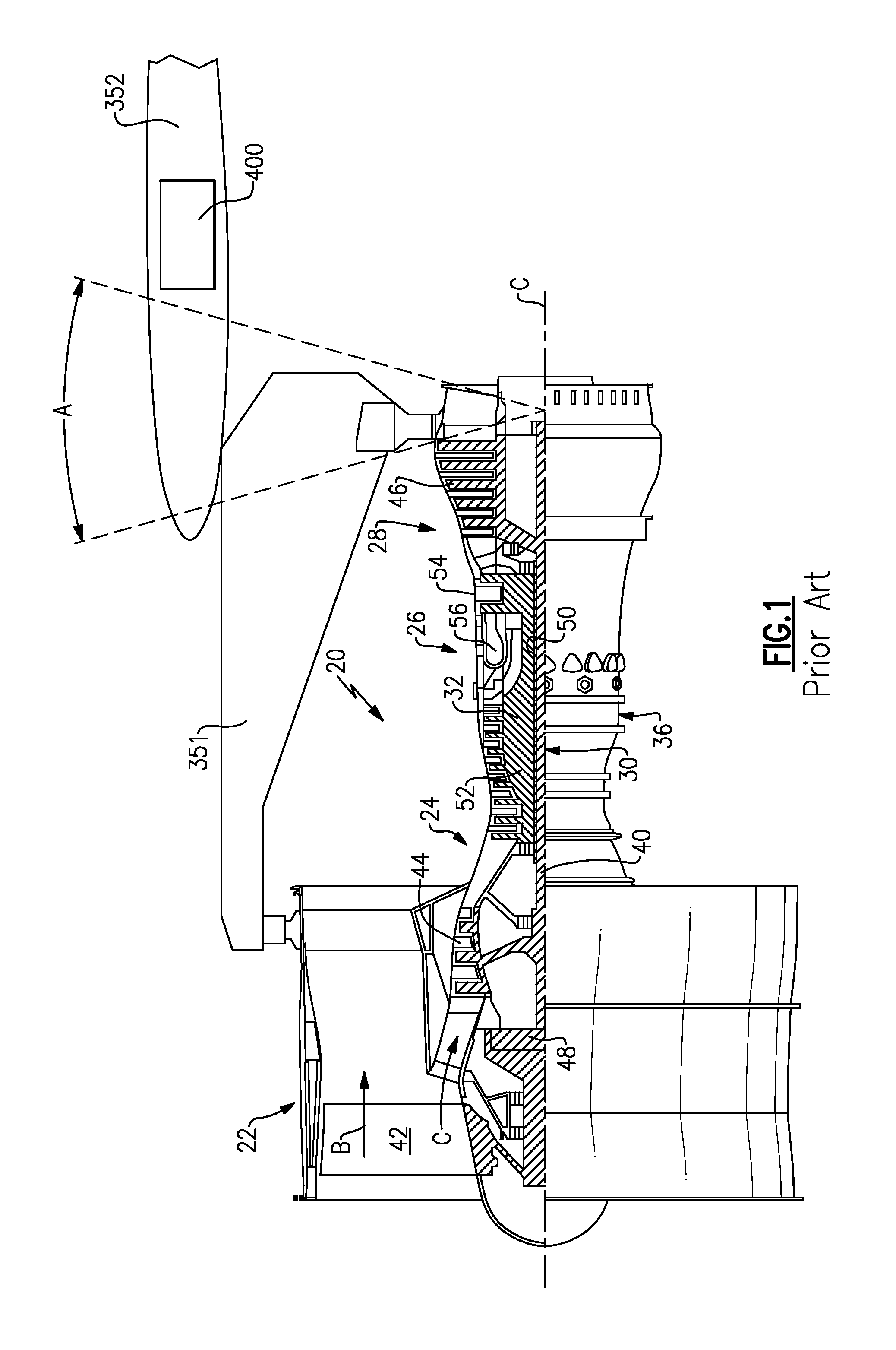
[0036]FIG. 1 schematically illustrates a known gas turbine engine 20. The gas turbine engine 20 is disclosed herein as a two-spool turbofan that generally incorporates a fan section 22, a compressor section 24, a combustor section 26 and a turbine section 28. Alternative engines might include an augmentor section (not shown) among other systems or features. The fan section 22 drives air along a bypass flowpath while the compressor section 24 drives air along a core flowpath for compression and communication into the combustor section 26 then expansion through the turbine section 28. Although depicted as a turbofan gas turbine engine in the disclosed non-limiting embodiment, it should be understood that the concepts described herein are not limited to use with turbofans as the teachings may be applied to other types of turbine engines including three-spool architectures.

[0037]The engine 20 generally includes a low speed spool 30 and a high speed spool 32 mounted for rotation about an...


PUM


Abstract

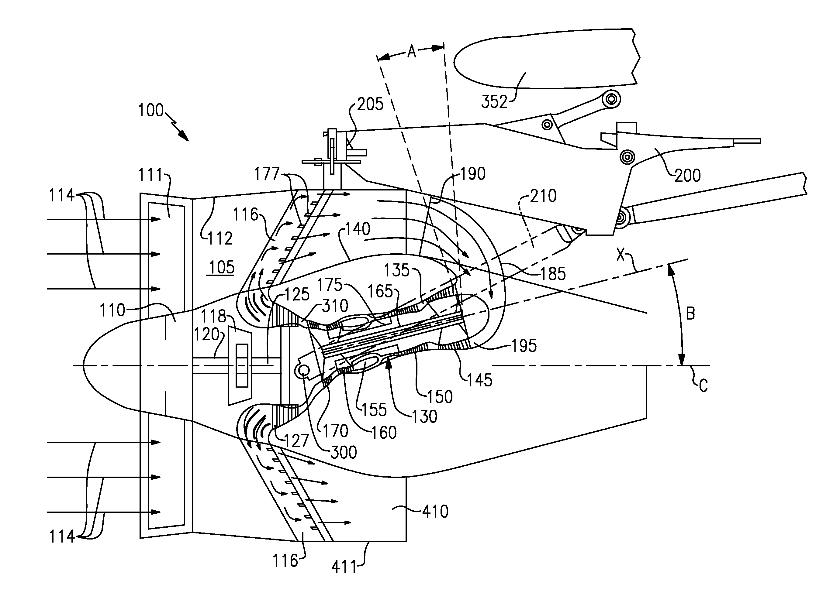
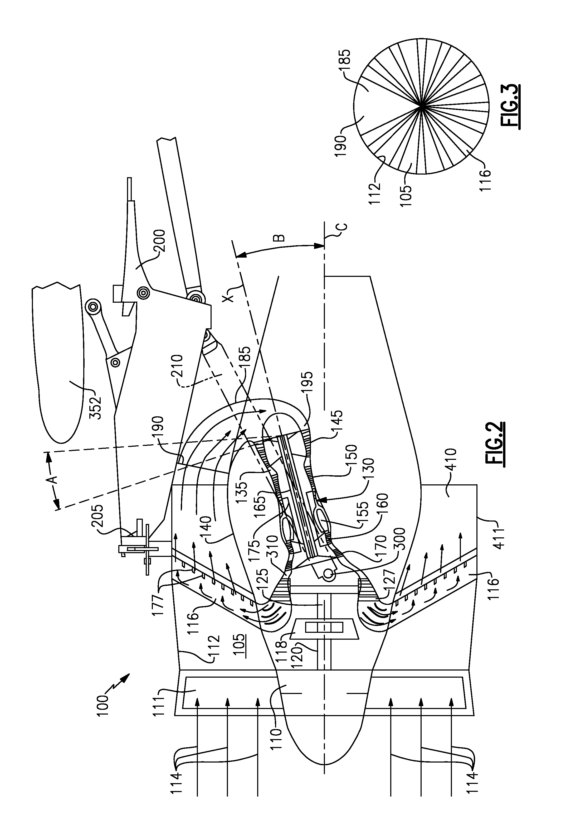
A gas turbine engine includes a propulsion unit mounted to rotate about a first axis, and a core engine mounted to rotate about a second axis, and wherein the first and second axes are non-parallel. A gas turbine engine includes a propulsion unit driven by a free turbine which is adjacent to the propulsion unit and an associated fan, and having a gas generator core engine including a compressor, combustor and turbine section. A method is also disclosed.

Description

BACKGROUND OF THE INVENTION[0001]This application relates to a gas turbine engine, wherein a core engine is mounted separately from a propulsion unit.[0002]Gas turbine engines are known, and have typically included a fan delivering a portion of air into a bypass duct, and a second portion of air into a core flow leading into a compressor section. The air is compressed in the compressor and delivered downstream into a combustion section where it is mixed with fuel and ignited. Products of this combustion pass across turbine rotors which are driven to rotate, and in turn rotate the compressor and fan section. Historically one turbine section drove both a compressor stage and a fan at the same speed. More recently it has been proposed to incorporate a gear reduction such as the fan can rotate at slower speeds than the compressor stage. With this arrangement, the outer diameter of the fan can increase, and the outer diameter of the turbine and compressor sections can decrease.[0003]Hist...

Claims


Application Information

Patent Timeline
IPC IPC(8): F02K3/02
CPCF02K3/025F05D2250/314F02C7/36F02C3/145
Inventor SUCIU, GABRIEL L.LORD, WESLEY K.DYE, CHRISTOPHER M.
Owner RAYTHEON TECH CORP
Learn More