Methods and systems for fuel vapor control

a technology of pressure control and fuel vapor, which is applied in the direction of combustion air/fuel air treatment, machines/engines, mechanical equipment, etc., can solve the problems of increasing hydrocarbon emission to the atmosphere, insufficient purging of fuel vapor from a vapor canister coupled between, etc., to reduce engine operation times, reduce regulated emissions benefits, and shorten engine operation times

Inactive Publication Date: 2013-08-15
FORD GLOBAL TECH LLC
View PDF70 Cites 16 Cited by
  • Summary
  • Abstract
  • Description
  • Claims
  • Application Information

AI Technical Summary

Benefits of technology

[0002]Reduced engine operation times in hybrid vehicles enable fuel economy and reduced regulated emissions benefits. However, the shorter engine operation times combined with low intake manifold vacuum may lead to insufficient purging of fuel vapor from a vapor canister coupled betw

Problems solved by technology

However, the shorter engine operation times combined with low intake manifold vacuum may lead to insufficient purging of fuel vapor from a vapor canister coupled between the intake manifold and the fuel tank.
Further, during

Method used


Image

  • Methods and systems for fuel vapor control
  • Methods and systems for fuel vapor control
  • Methods and systems for fuel vapor control

Examples


Embodiment Construction

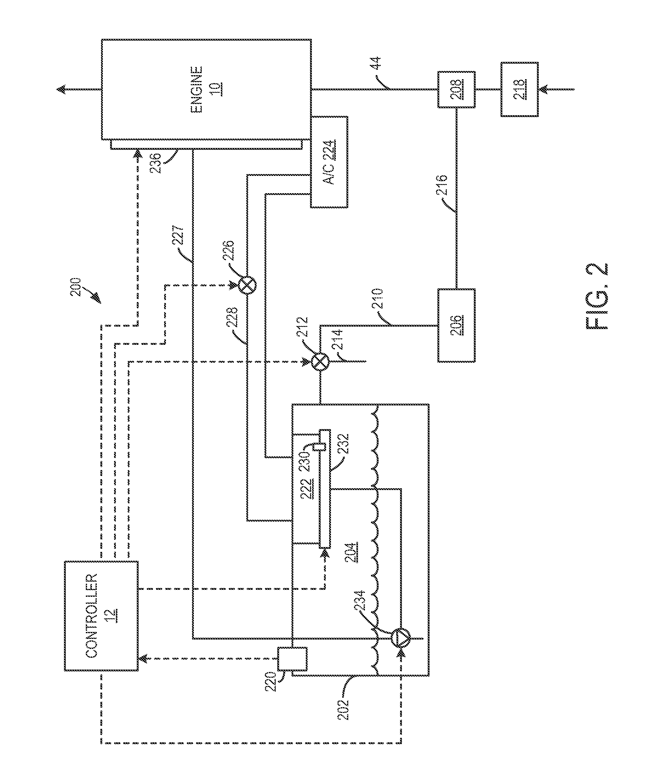
[0012]The following description relates to various embodiments of methods and systems for controlling pressure in a fuel tank. In one example, a method for a fuel system comprises, responsive to an operating condition, condensing fuel vapor in a vapor cooler disposed in a fuel tank and routing condensed fuel vapor to a fuel pump or pressurized fuel line between the fuel pump and injectors. For example, the vapor cooler may be fluidly coupled to a cooling system such that heat exchange may occur between fuel vapors in the fuel tank and cooling fluid circulating through the vapor cooler. In this manner, fuel vapor in the fuel tank may be condensed such that a pressure in the fuel tank is decreased under conditions when the fuel tank pressure is high, such as under relatively high ambient temperatures. Further, in another embodiment, cooling system operation may be adjusted based on the fuel tank. Various examples will be described in greater detail herein.

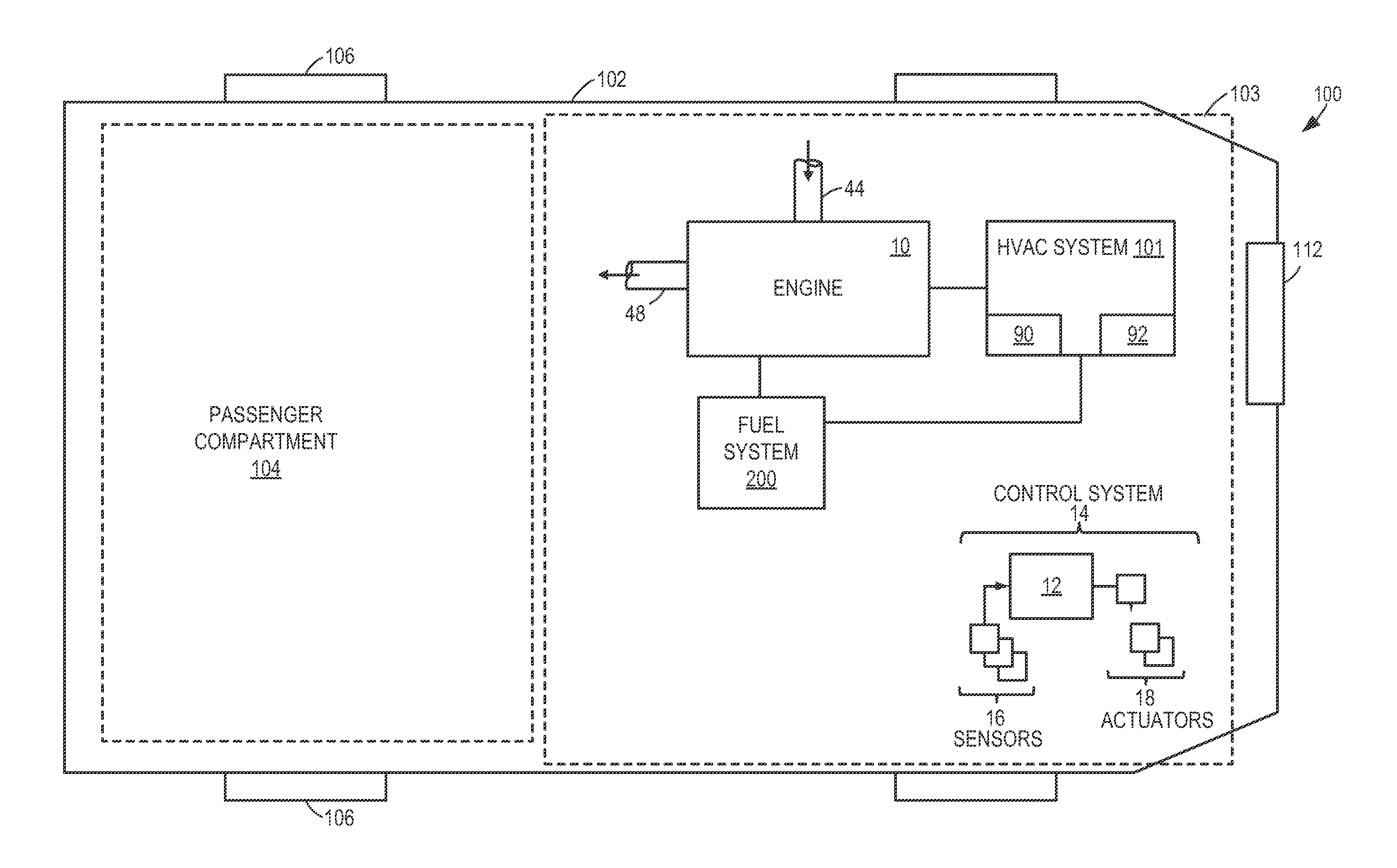
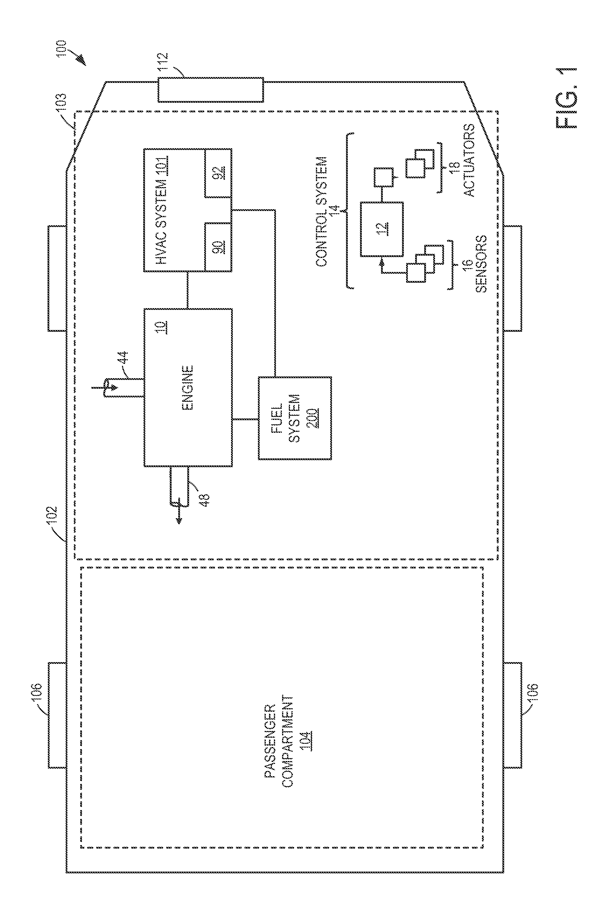
[0013]FIG. 1 shows a schemati...


PUM


Abstract

Various methods and systems are provided for reducing pressure in a fuel tank of a fuel system of an engine. In one example, cooling fluid is routed from an air conditioner of a cooling system to a vapor cooler disposed in a vapor space of the fuel tank such that fuel vapor in the fuel tank may be condensed and routed to a fuel pump for delivery to the engine, thereby reducing a fuel tank pressure.

Description

TECHNICAL FIELD[0001]The present application relates to pressure control in fuel tanks in vehicles such as hybrid vehicles.BACKGROUND AND SUMMARY[0002]Reduced engine operation times in hybrid vehicles enable fuel economy and reduced regulated emissions benefits. However, the shorter engine operation times combined with low intake manifold vacuum may lead to insufficient purging of fuel vapor from a vapor canister coupled between the intake manifold and the fuel tank. Further, during conditions such as relatively warm ambient temperatures when fuel vapor generation in the fuel tank is increased, insufficient purging of the vapor canister may result in an increase in hydrocarbon emission to the atmosphere.[0003]The inventors herein have recognized the above issue and have devised an approach to at least partly address it. In one example, a method for a fuel system is provided. The method includes, responsive to an operating condition, condensing fuel vapor in a vapor cooler disposed i...

Claims


Application Information

Patent Timeline
IPC IPC(8): F02M33/02
CPCF02M31/20Y02T10/126F02M2025/0863Y02T10/12
Inventor KRAGH, NIELS CHRISTOPHER
Owner FORD GLOBAL TECH LLC
Why Eureka
Try Eureka