Coupler

a technology of couplers and bearings, applied in the field of couplers, can solve the problems of coupler fatigue failure, coupler assembly, draw load, etc., and achieve the effects of increasing the bearing area, increasing the load capacity of the coupler, and increasing the bearing area

Inactive Publication Date: 2013-08-15
BRADKEN RESOURCES
View PDF2 Cites 9 Cited by
  • Summary
  • Abstract
  • Description
  • Claims
  • Application Information

AI Technical Summary

Benefits of technology

[0006]In accordance with the first aspect the latch member comprises a protruding portion for receipt in a recess of the head. The protruding portion comprises at least two adjacent projecting lugs, and the recess comprises at least two corresponding adjacent shoulders behind which each lug is located when the latch member protruding portion is received in the head recess. Such a configuration can increase the bearing area between the latch member and the coupler head, to increase the coupler's load capacity, to prolong its life and to extend its fatigue resistance. Such a configuration can also significantly reduce the concentration of stress during wagon draw in the vicinity of the lower interface between the latch member and the coupler head.
[0027]In this regard, the block is able to drop into the locked position, with the tapered mating faces always contacting each other. Block oversize and undersize issues can arise during block manufacture. In the case of an oversize block, the block will drop in to a lesser extent, and in the case of an undersize block the block will drop further before coming to a wedged, locked position. However, the tapered locking block is able to drop over the life of the coupler, compensating for wear on the fit faces, and maintaining a slack-less, locked condition. Reducing or eliminating slack in the latch locking mechanism has been observed to reduce dynamic impulse loads during coupler service. This reduction in dynamic loads improves the fatigue life, not only of coupler components, but also of other drawgear components. Thus, the block is able to form a tight fit, and can continue to restrain the latch member in the closed position, over time.

Problems solved by technology

In the deployment of rail wagons, draw loads are often responsible for fatigue failure in the coupler.
Another dominant failure mechanism of the coupler assembly is fatigue failure of the knuckle through its so-called knuckle “palm”.

Method used


Image

  • Coupler
  • Coupler
  • Coupler

Examples


Embodiment Construction

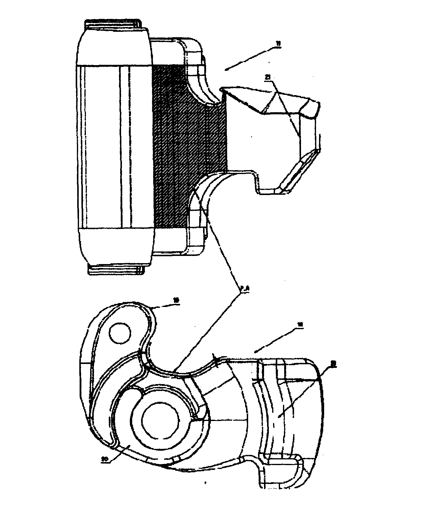
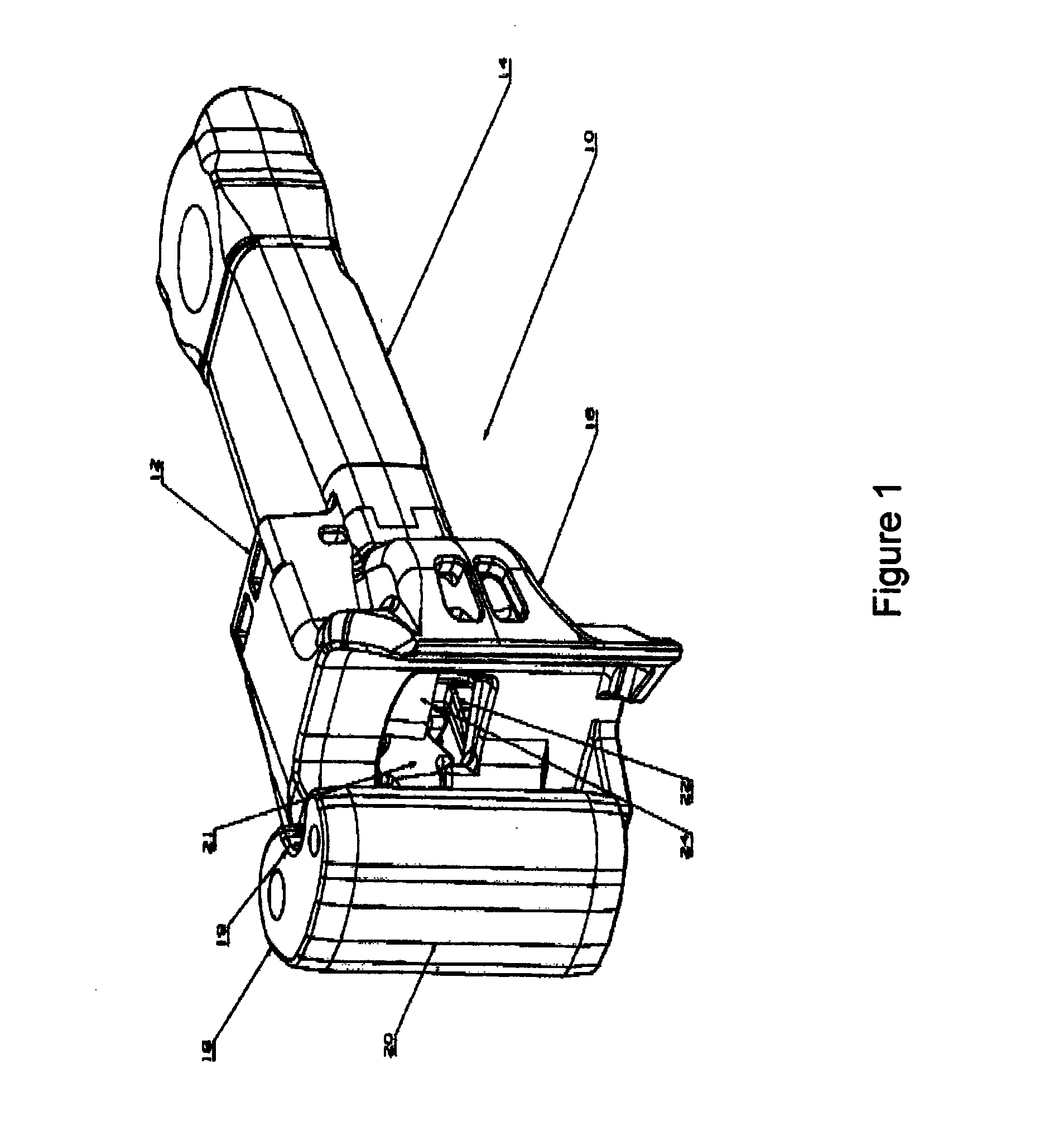
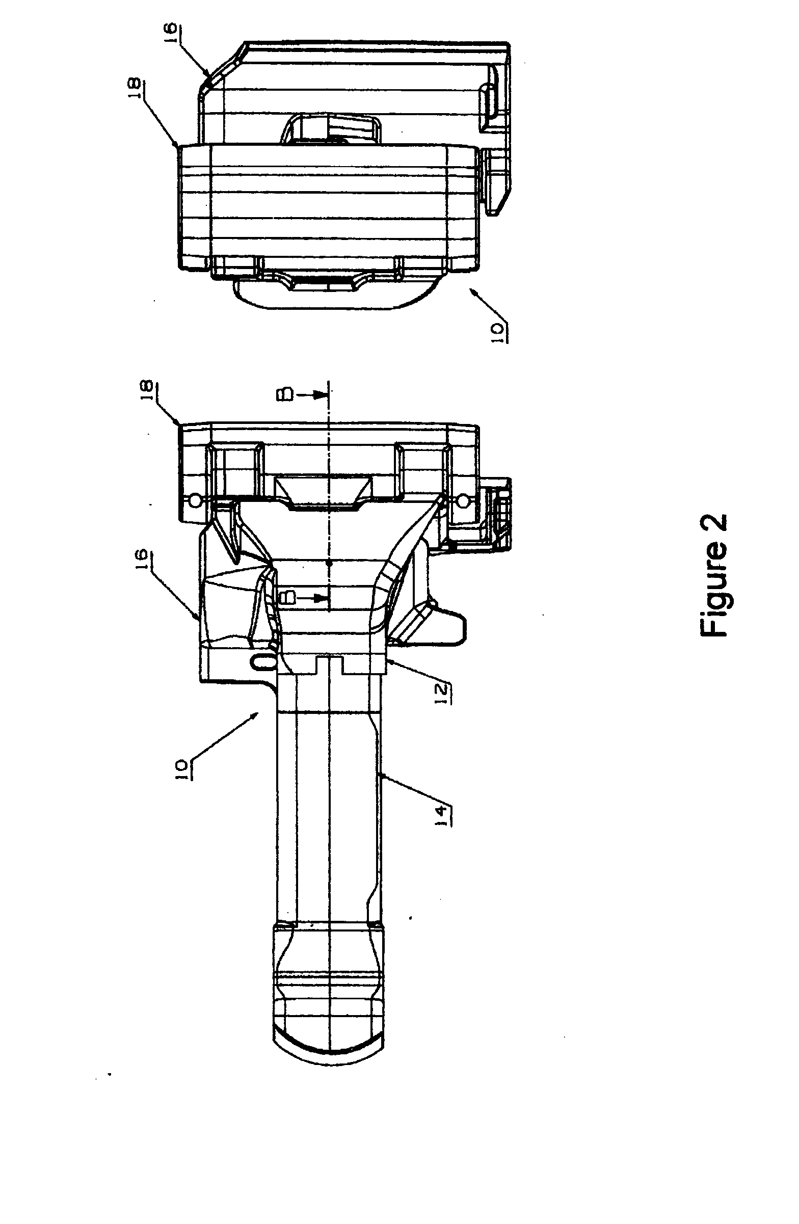
[0055]Referring firstly to FIG. 1, a rail wagon coupler 10 includes a coupler body 12 cast as a single unit from alloyed steel. The body 12 comprises a shank 14 and an integral head 16 located at an end of the shank 14. A coupler latch member in the form of a knuckle 18 is pivotally mounted to an end of the head 16. The knuckle 18 comprises a latching portion 19 extending from an elongate knuckle body 20 that pivots on the head about an elongate axis. The knuckle is also cast as a single unit from alloyed steel, though the grade may vary (e.g. be improved) from that employed for the coupler body.

[0056]Coupler 10 is an automatic-type coupler, in that it automatically latches (i.e. via latching portion 19) with an opposing like-coupler when two rail wagons are buffed together. The coupler functions to join the two wagons and in use transmits both buff (compressive) and draw (tensile) loads between the wagons. The draw loads are the main loads responsible for fatigue failures in the co...


PUM


Abstract

A coupler for a rail wagon includes a coupler body. The body includes a shank and a head located at an end of the shank. A coupler latch member is mounted to an end of the head. The latch member includes a protruding portion for receipt in a recess of the head. The protruding portion includes at least two adjacent projecting lugs, and the recess includes at least two corresponding adjacent shoulders behind which each lug is located when the latch member protruding portion is received in the head recess.

Description

CROSS-REFERENCE TO RELATED APPLICATIONS[0001]This application is a national stage application under 35 USC 371 of International Application No. PCT / AU2011 / 001048, filed Aug. 17, 2011, which claims the priority of Australian Application No. AU 2010903691, filed Aug. 17, 2010, the contents of which prior applications are incorporated herein by reference.FIELD OF THE INVENTION[0002]An improved coupler for a rail wagon is disclosed. The coupler can take the form of an automatic-type coupler which automatically latches with an opposing coupler to join the two wagons when they are buffed together. The coupler can transmit both buff (compressive) and draw (tensile) loads between the wagons in use.BACKGROUND OF THE INVENTION[0003]In the deployment of rail wagons, draw loads are often responsible for fatigue failure in the coupler. These draw loads are transmitted through a so-called knuckle and into a body of the coupler, via a single upper pulling lug and a single lower pulling lug. These ...

Claims


Application Information

Patent Timeline
Patent Type & Authority Applications(United States)
IPC IPC(8): B61G3/04
CPCB61G3/06B61G3/04
Inventor BURGOYNE, SIMONSANSOM, TIMOTHY
Owner BRADKEN RESOURCES
Why Eureka
Try Eureka