Synchronous motor

a synchronous motor and synchronous technology, applied in the direction of dynamo-electric machines, magnetic circuit rotating parts, magnetic circuit shapes/forms/construction, etc., can solve the problem of reducing the output torque of the patent document, difficult in principle for such ferrite magnets to generate a large output torque, and electric motors as the conventional technique disclosed

Inactive Publication Date: 2013-08-15
DENSO CORP
View PDF8 Cites 22 Cited by
  • Summary
  • Abstract
  • Description
  • Claims
  • Application Information

AI Technical Summary

Benefits of technology

[0024]This structure makes it possible to obstruct the magnetic field, similar to the case in which the magnetic field is obstructed by the teeth around which the outer stator winding is wound and the inner stator winding is wound, where the outer stator winding and the inner stator winding are power sources to provide magnetomotive force in order to generate a magnetic field.
[0025]According to the present invention, the structure of the double stator synchronous motor having the structure previously described and which will be explained later in detail, can pass necessary magnetic flux and obstruct unnecessary magnetic field, and generate high output torque.

Problems solved by technology

However, the electric motor as the conventional technique disclosed in the conventional patent document has a decreased output torque when using ferrite magnets instead of using neodymium magnets arranged between adjacent segment magnetic poles because such ferrite magnets have a low magnetic flux density which is smaller than a magnetic flux density of neodymium magnets.
That is, because ferrite magnets have a low residual magnetic flux density and low coercive force, it is difficult in principle for such ferrite magnets to generate a large output torque in a limited space of an electric motor, as compared with the output torque when using neodymium magnets.

Method used


Image

  • Synchronous motor
  • Synchronous motor
  • Synchronous motor

Examples


first exemplary embodiment

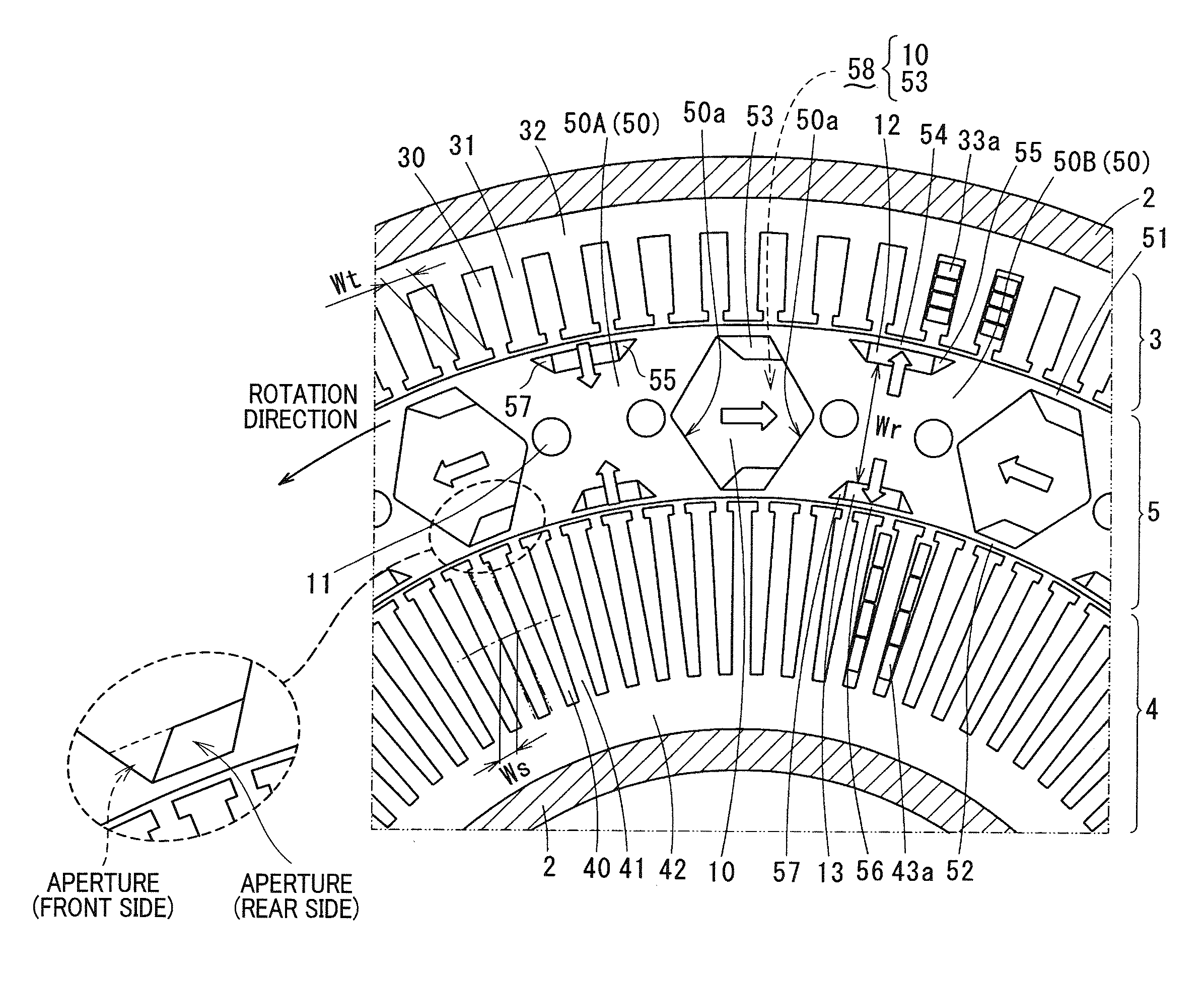
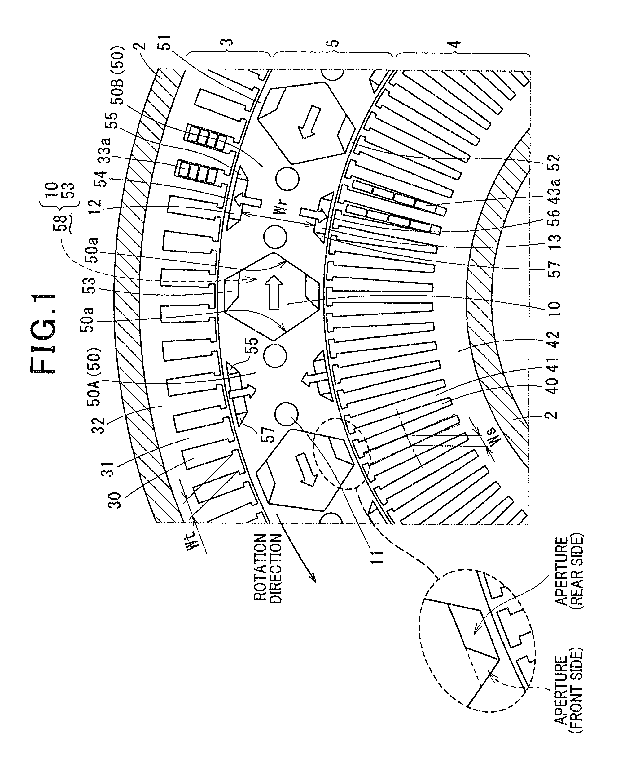
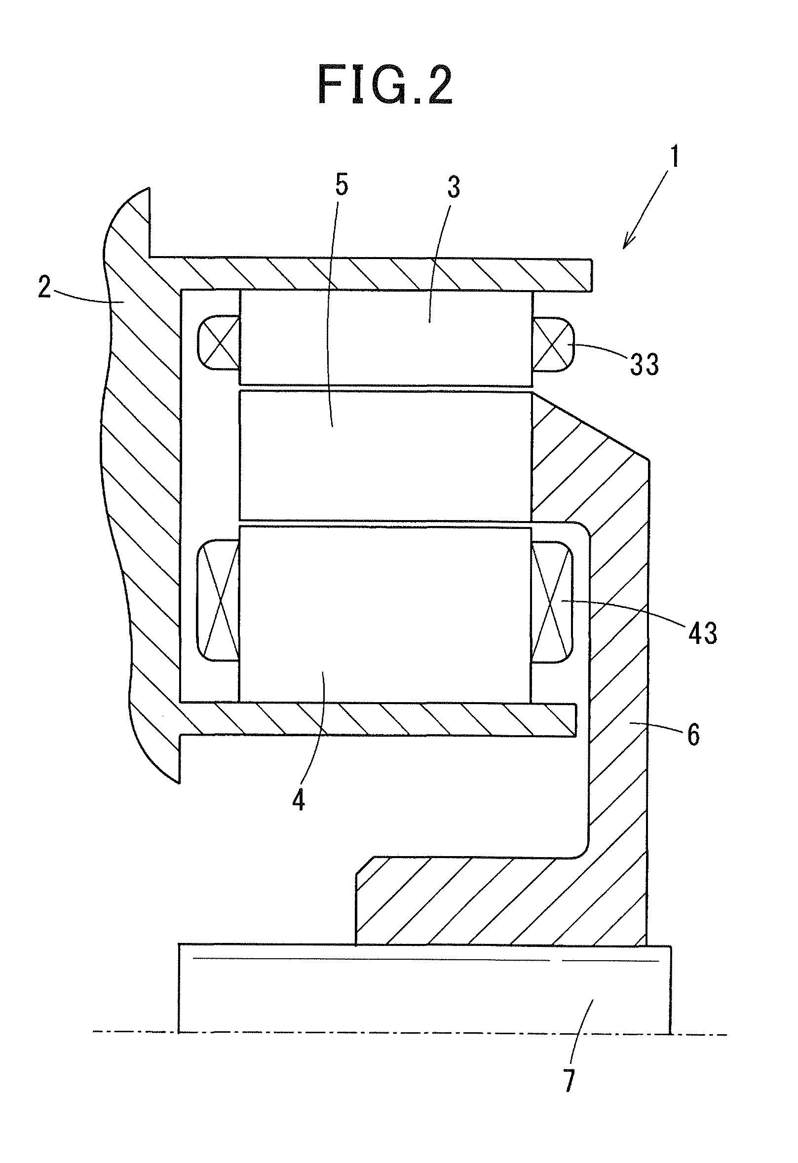
[0038]At first, the concept of the present invention relates to a synchronous motor, for example, a double stator synchronous motor. Such a double stator synchronous motor has a rotor and a stator assembly composed of a first stator and a second stator. In a structure of one stator assembly, the first stator and the second stator are arranged at both sides in an axial direction of the rotor. In a structure of the other stator assembly, the first stator is arranged at a radially outside section of the rotor, and the second stator is arranged at a radially inner section of the rotor. The following explanation of the first exemplary embodiment will explain the latter case of the stator assembly in which an outer stator as the first stator is arranged at a radially outside section of the rotor, and an inner stator as the second stator is arranged at a radially inner section of the rotor.

[0039]A description will be given of a double stator synchronous motor 1 according to the first exemp...

second exemplary embodiment

[0136]A description will be given of the double stator synchronous motor according to a second exemplary embodiment with reference to FIG. 6.

[0137]FIG. 6 is a view showing a partial cross section of the double stator synchronous motor according to the second exemplary embodiment of the present invention.

[0138]As shown in FIG. 6, an outer aperture section 53a1 is formed in an overall width area (which is composed of a front side area and a rear side area) between the adjacent segment magnetic poles 50 along a rotation direction of the rotor 5. That is, the outer aperture section 53a1 is formed in an overall width area between the adjacent segment magnetic poles 50, namely, between one segment magnetic pole 50A and the other segment magnetic pole 50B, and also between the magnetic-pole outside bridge 51 (at the upper side) and the buried magnet 10.

[0139]Similar to the outer aperture section 53a1, an inner aperture section 53a2 is formed in an overall width area (which is composed of a...

third exemplary embodiment

[0142]A description will be given of the double stator synchronous motor according to a third exemplary embodiment with reference to FIG. 7.

[0143]FIG. 7 is a view showing a partial cross section of the double stator synchronous motor according to the third exemplary embodiment of the present invention.

[0144]As shown in FIG. 7, the magnetic-pole central magnet 13 is arranged in the inner diameter side of the segment magnetic pole 50.

[0145]The outer magnetic concave section (or an outer magnetic depressed section) is formed on an outer diameter side of the segment magnetic pole 50. The outer magnetic concave section is formed as a concave area 59 from the outermost diameter side toward an inner diameter side. The structure using the concave section 59 makes it possible to concentrate the magnetic-pole central magnet 13, as compared with the structure having both the magnetic-pole central magnet 13 formed at the radially inner side and the magnetic-pole central magnet 12 arranged at th...


PUM


Abstract

A double-stator synchronous motor has a rotor, an inner stator and an outer stator. The rotor has segment-magnetic poles arranged in a ring shape. Magnetic poles formed in the inner stator and the outer stator face to each other in a same circumferential position. Each stator has q (q≧2) slots per pole and phase to disperse magnetomodive force. A radially minimum width Wr of each segment magnetic pole is within a range of 1.3q to 2.3q times of a minimum width Wt of outer teeth. A magnetic depth of a magnetic concave section formed in the segment magnetic pole is within a range of not less than an average width Ws of the inner slots. Because this suppresses demagnetization in the permanent magnets caused by stator magnetomotive force, ferrite magnets are used as buried magnets and magnetic-pole central magnets, and suppress the amount of neodymium magnet used in the rotor.

Description

CROSS-REFERENCE TO RELATED APPLICATION[0001]This application is related to and claims priority from Japanese Patent Application No. 2012-027910 filed on Feb. 13, 2012, the contents of which are hereby incorporated by reference.BACKGROUND OF THE INVENTION[0002]1. Field of the Invention[0003]The present invention relates to synchronous motors to be used for various industrial devices and hybrid electric vehicles, etc., and more particularly, relates to double stator synchronous motors having a double stator structure and which consume a less amount of rare earth magnets or no rare earth magnet by using ferrite magnets instead of rare earth magnets.[0004]2. Description of the Related Art[0005]There are known double stator electric motors having a double stator structure composed of an outer stator, an inner stator and a rotor. In a conventional double stator electric motor, the outer stator is disposed on a radially outer side of the stator and the inner stator is disposed on a radiall...

Claims


Application Information

Patent Timeline
Patent Type & Authority Applications(United States)
IPC IPC(8): H02K1/27H02K16/04H02K1/16
CPCH02K1/16H02K1/2706H02K16/04H02K16/00H02K1/27H02K2213/03H02K21/12
Inventor KUSASE, SHINKONDOU, KEIJI
Owner DENSO CORP
Why Eureka
Try Eureka