Switching Power Supply Circuit

Inactive Publication Date: 2013-08-15
SANKEN ELECTRIC CO LTD
View PDF2 Cites 11 Cited by
  • Summary
  • Abstract
  • Description
  • Claims
  • Application Information

AI Technical Summary

Benefits of technology

[0010]According to this disclosure, it is possible to provide the sw

Problems solved by technology

Therefore, a switching loss is caused in the switching ele

Method used


Image

  • Switching Power Supply Circuit
  • Switching Power Supply Circuit
  • Switching Power Supply Circuit

Examples


Embodiment Construction

[0018]Hereinafter, switching power supply circuits of illustrative embodiments of this disclosure will be described with reference to the drawings.

First Illustrative Embodiment

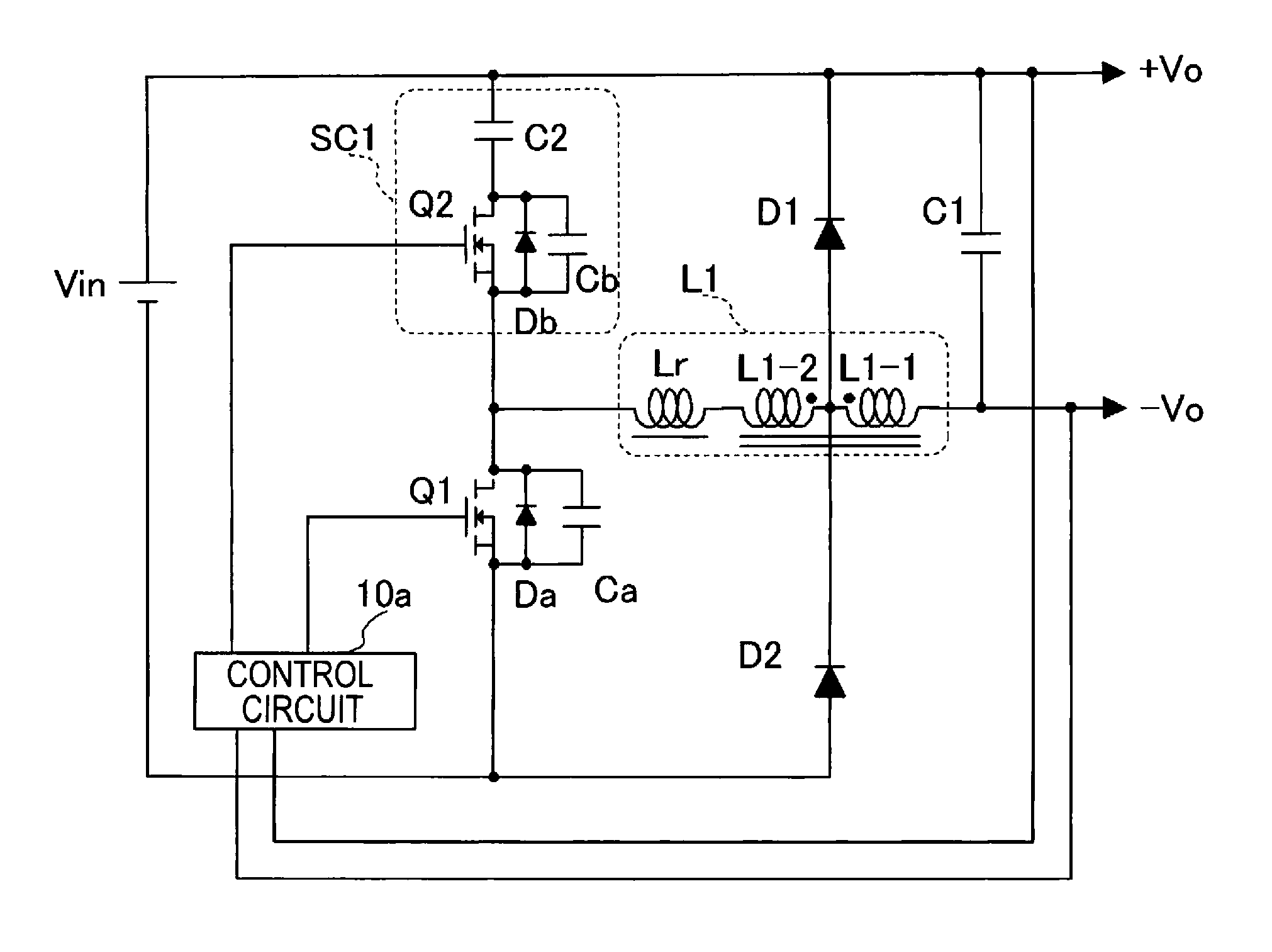
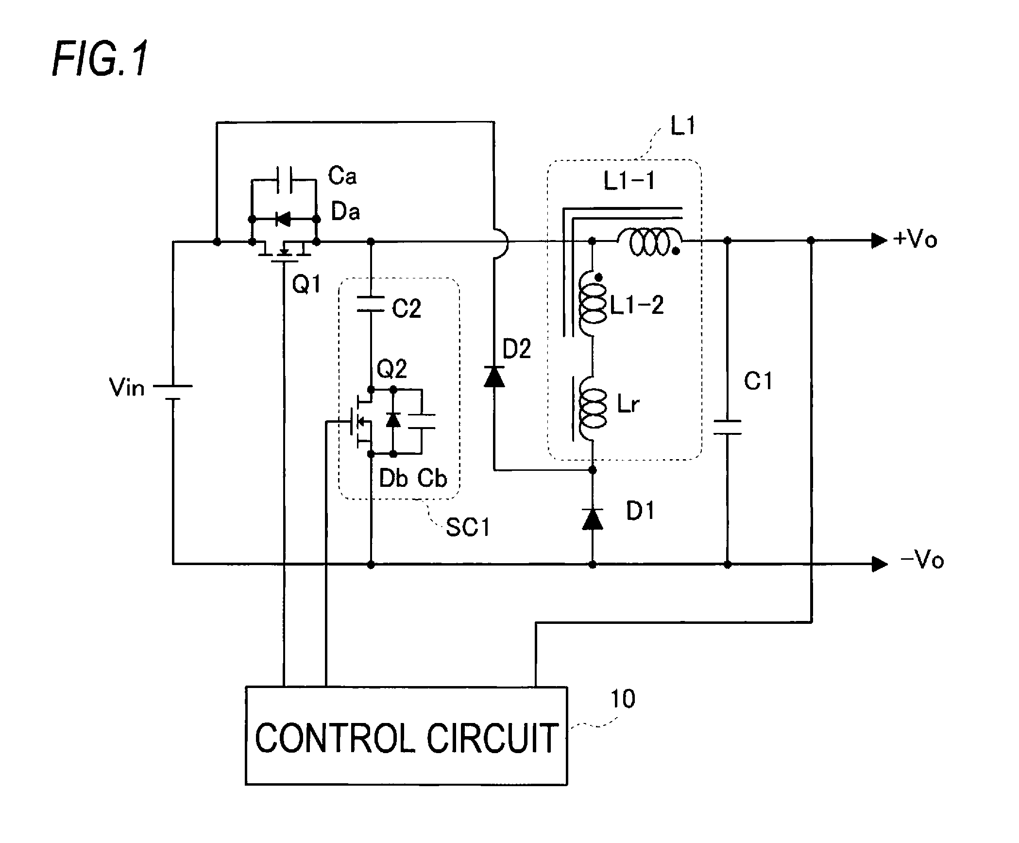
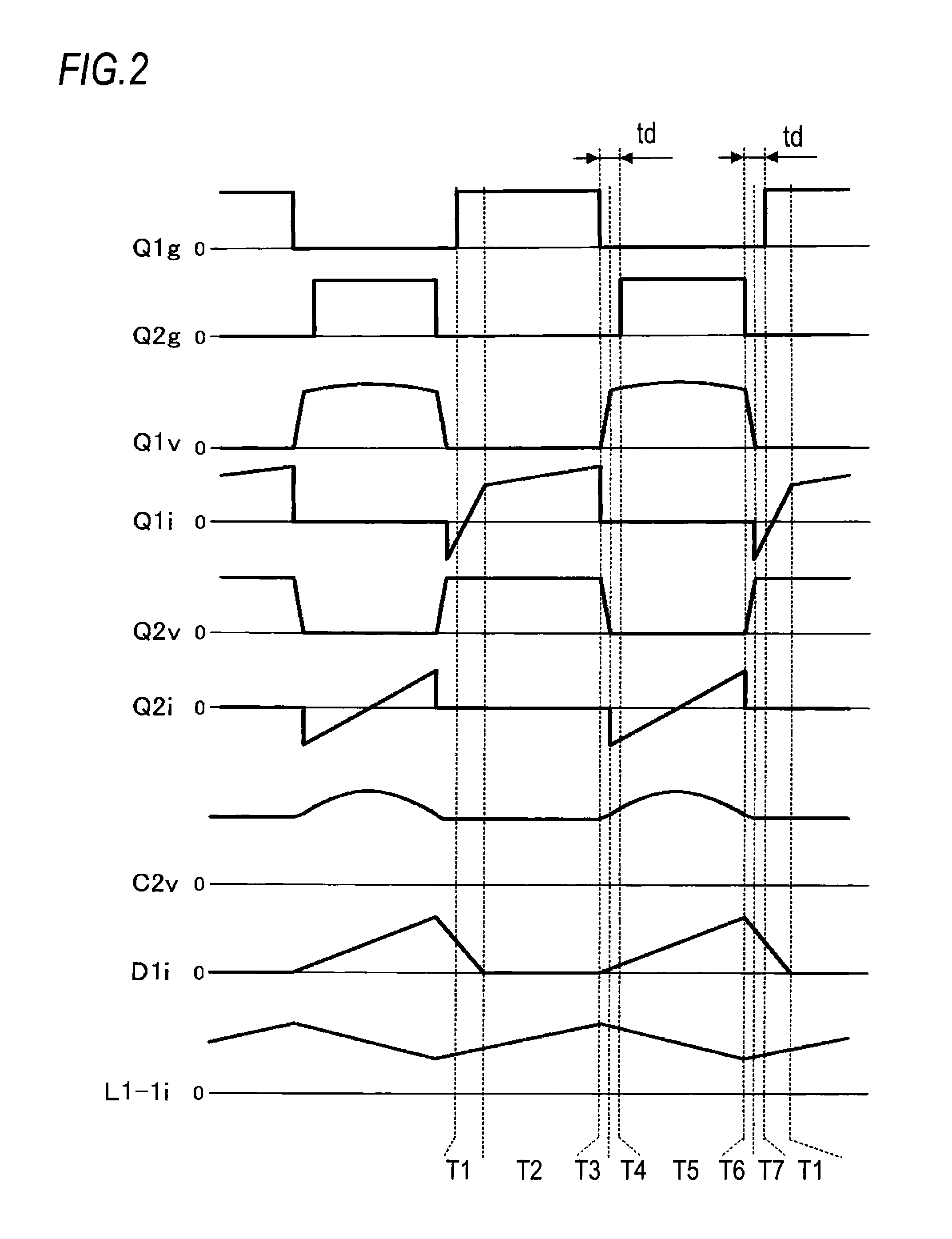
[0019]FIG. 1 illustrates a switching power supply circuit according to a first illustrative embodiment of this disclosure. The switching power supply circuit shown in FIG. 1 is a step-down switching power supply circuit that outputs an output voltage Vo having a predetermined value lower than a voltage (input voltage) of a direct current power supply Vin, and has a reactor L1, a switching element Q1, a switching element Q2, a smoothing capacitor C1, a resonance capacitor C2, a diode D1 (first diode), a diode D2 (second diode) and a control circuit 10.

[0020]The reactor L1 has a main winding L1-1 and an auxiliary winding L1-2 having a leakage inductance Lr, which are magnetically coupled with each other and are connected with each other at one ends thereof. The leakage inductance Lr is generated so that it is eq...


PUM


Abstract

A switching power supply circuit includes: a reactor that has a main winding and an auxiliary winding having a leakage inductance, which are magnetically coupled with each other and are connected with each other at one ends thereof; a first series circuit, which has an auxiliary switch and a resonance capacitor connected in series, and which is connected in parallel with a direct current power supply via a main switch; a first diode that, which is connected in parallel with the first series circuit via the auxiliary winding; a smoothing capacitor, which is connected in parallel with at least one of the first series circuit and first diode via the main winding; and a control circuit, which alternately turns on and off the main switch and auxiliary switch to thus control an output voltage of the smoothing capacitor to be a predetermined value.

Description

CROSS-REFERENCE TO RELATED APPLICATION[0001]This application claims priority from Japanese Patent Application No. 2012-030361 filed on Feb. 15, 2012 the entire subject matter of which is incorporated herein by reference.TECHNICAL FIELD[0002]This disclosure relates to a switching power supply circuit capable of reducing a switching loss.BACKGROUND ART[0003]A step-down switching power supply circuit has been known. FIG. 6 illustrates an example of the step-down switching power supply circuit of the background art. In FIG. 6, a series circuit of a switching element Q10, a reactor L10 and a smoothing capacitor C10 is connected to both terminals of a direct current power supply Vin. Also, a diode D10 as a free-wheeling diode is connected to a connection point of the switching element Q10 and the reactor L10 and to a negative terminal of the direct current power supply Vin.[0004]A control circuit 100 detects an output voltage Vo from the smoothing capacitor C10 and controls an on-off oper...

Claims


Application Information

Patent Timeline
IPC IPC(8): G05F1/46
CPCG05F1/468H02M1/34H02M3/158Y02B70/10H02M1/342
Inventor CHIBA, AKITERU
Owner SANKEN ELECTRIC CO LTD
Why Eureka
Try Eureka