High-frequency signal transmission line and electronic apparatus including the same

Active Publication Date: 2013-08-15
MURATA MFG CO LTD
View PDF11 Cites 25 Cited by
  • Summary
  • Abstract
  • Description
  • Claims
  • Application Information

AI Technical Summary

Benefits of technology

[0015]According to various preferred embodiments of the present invention,

Problems solved by technology

However, with the signal line 500 disclosed in PCT Publication No. 2011/01893

Method used


Image

  • High-frequency signal transmission line and electronic apparatus including the same
  • High-frequency signal transmission line and electronic apparatus including the same
  • High-frequency signal transmission line and electronic apparatus including the same

Examples


first preferred embodiment

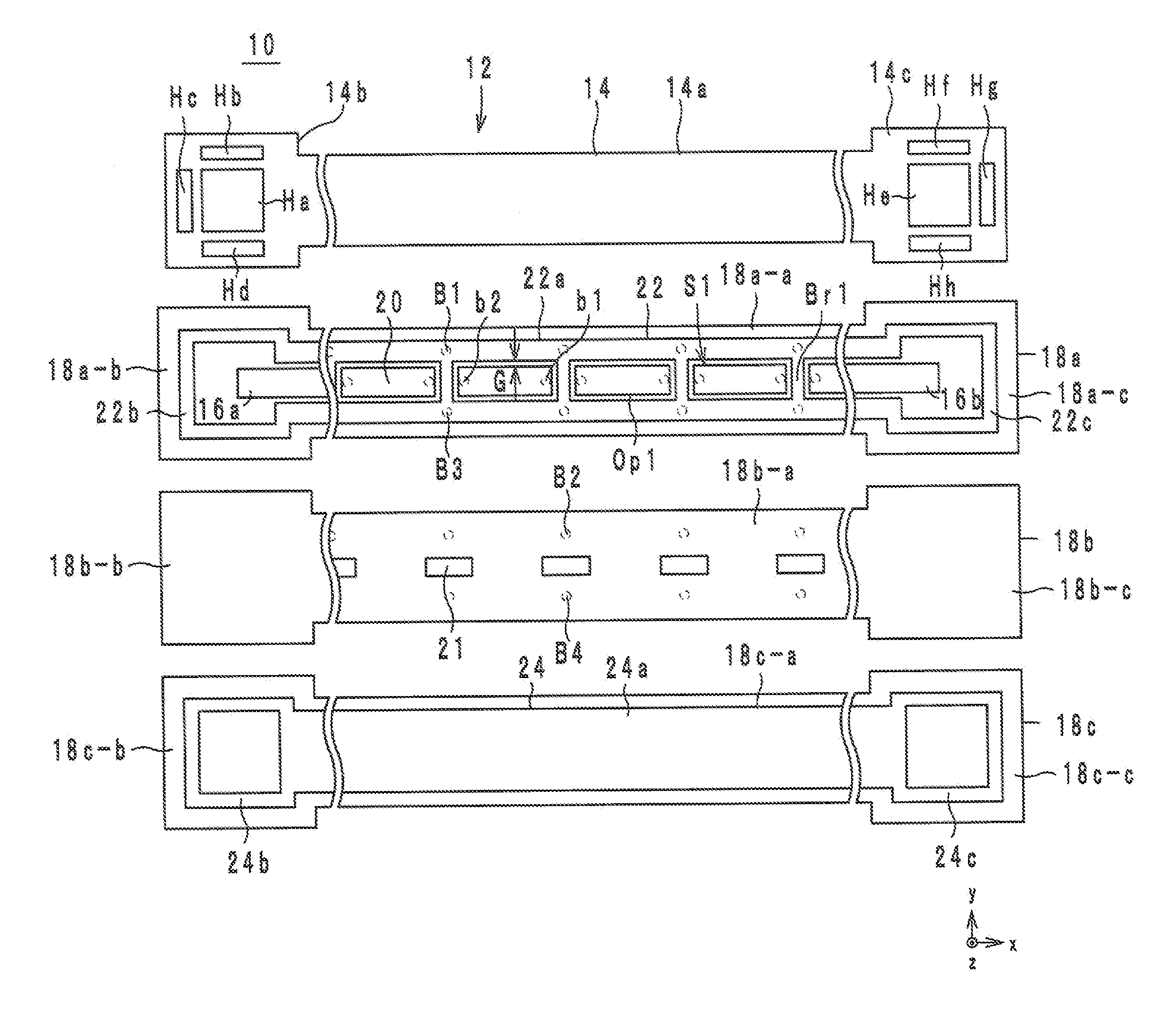
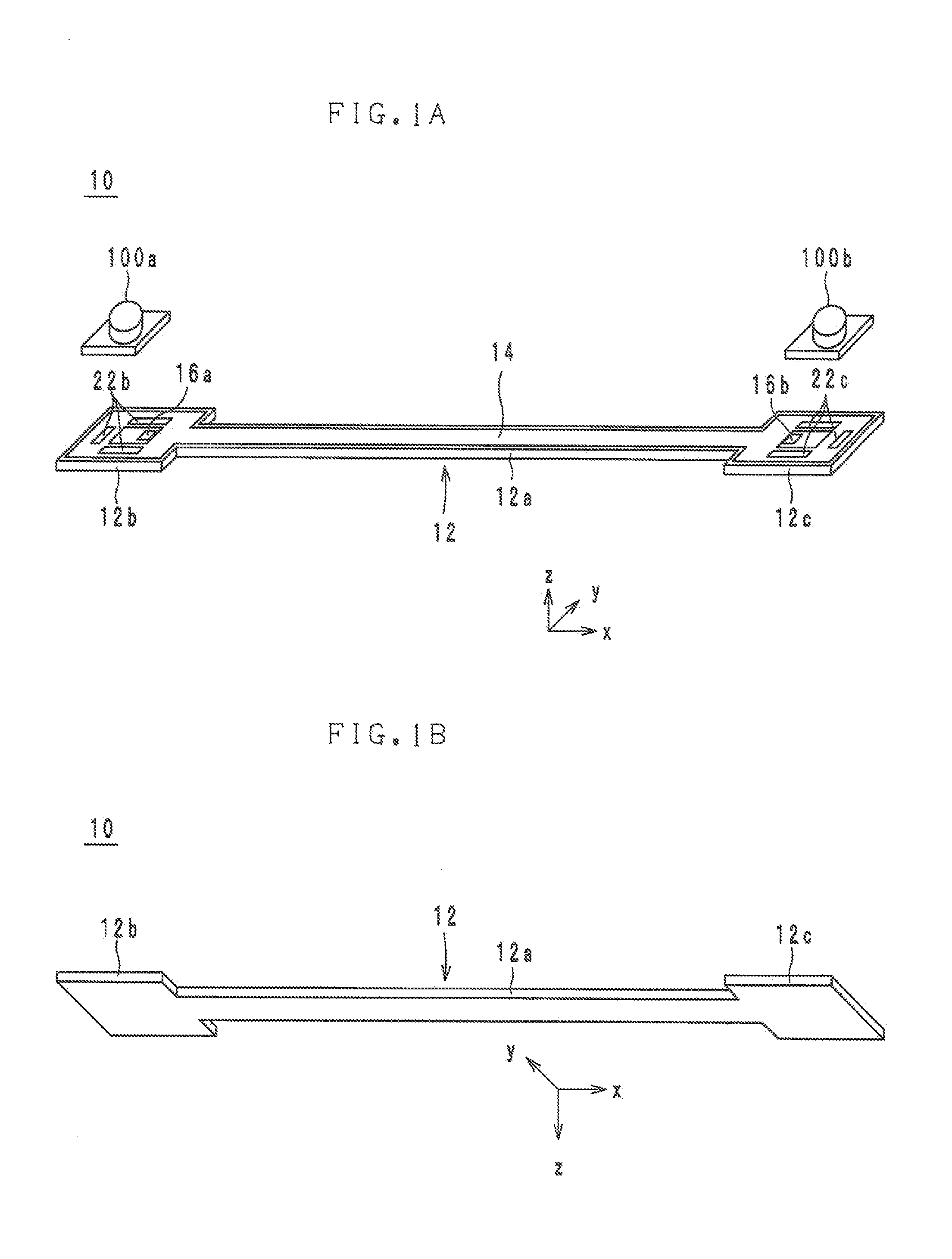
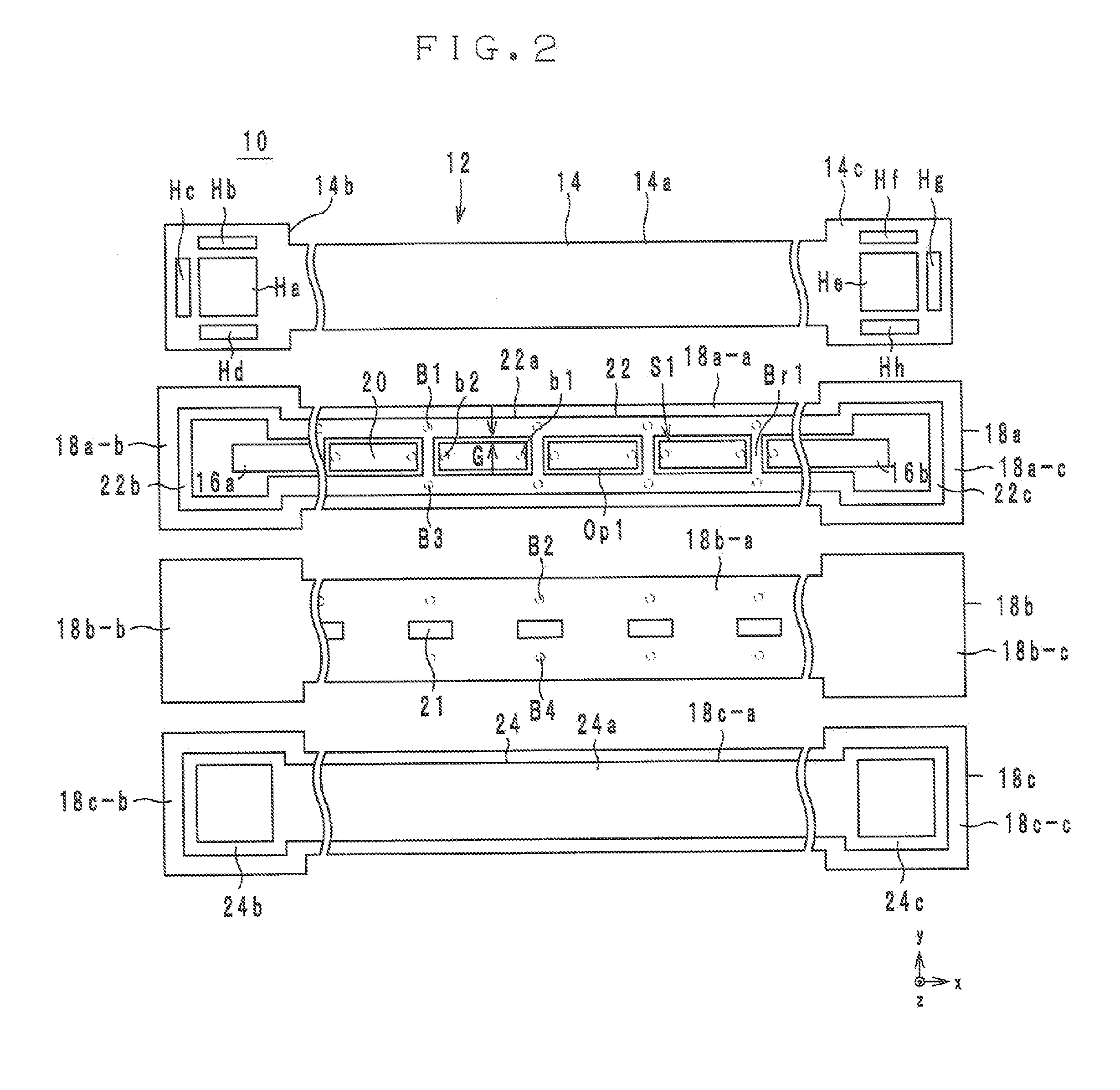
[0064]Hereinafter, a configuration of a high-frequency signal transmission line according to a first preferred embodiment of the present invention will be described with reference to drawings. FIGS. 1A and 1B are external perspective views of a high-frequency signal transmission line 10 according to the first preferred embodiment. FIG. 2 is an exploded view of the high-frequency signal transmission line 10 according to the first preferred embodiment. FIG. 3 is a cross-sectional configuration diagram of the high-frequency signal transmission line 10 according to the first preferred embodiment. FIG. 4 is a planar view of the high-frequency signal transmission line 10 according to the first preferred embodiment. FIGS. 5A to 5C are cross-sectional views of the high-frequency signal transmission line 10 according to the first preferred embodiment. FIG. 5A is a cross-sectional configuration diagram at A-A in FIG. 4. FIG. 5B is a cross-sectional configuration diagram at B-B in FIG. 4. FIG....

second preferred embodiment

[0155]Hereinafter, the configuration of a high-frequency signal transmission line according to a second preferred embodiment of the present invention will be described with reference to drawings. FIG. 12 is an exploded view of a high-frequency signal transmission line 10d according to the second preferred embodiment. In FIG. 12, the surface and rear surface of the dielectric sheet 18a are illustrated. FIG. 13 is a cross-sectional configuration diagram of the high-frequency signal transmission line 10d according to the second preferred embodiment. FIG. 14 is a planar view of the high-frequency signal transmission line 10d according to the second preferred embodiment. FIGS. 15A to 15C are cross-sectional configuration diagrams of the high-frequency signal transmission line 10d according to the second preferred embodiment. FIG. 15A is a cross-sectional view taken along A-A in FIG. 14. FIG. 15B is a cross-sectional view taken along B-B in FIG. 14. FIG. 15C is a cross-sectional view take...


PUM


Abstract

A high-frequency signal transmission line includes a body; a signal line including a first line portion provided to a first layer of the body, a second line portion provided to a second layer of the body alternately being connected; and a first ground conductor provided to the first layer or a third layer positioned on an opposite side of the second layer relative to the first layer, and also overlaid with a plurality of second line portions in planar view from a normal direction of a principal surface of the body, and also not overlaid with a plurality of the first line portions. A property impedance of the first line portion and a property impedance of the second line portion are different from each other.

Description

BACKGROUND OF THE INVENTION[0001]1. Field of the Invention[0002]The present invention relates to a high-frequency signal transmission line and an electronic apparatus including the same, and specifically relates to a high-frequency signal transmission line used for transmission of high-frequency signals, and an electronic apparatus including the same.[0003]2. Description of the Related Art[0004]A conventional high-frequency signal transmission line is disclosed in PCT Publication No. 2011 / 018934, for example. FIG. 46 is an exploded view of a signal line 500 disclosed in PCT Publication No. 2011 / 018934.[0005]The signal line 500 illustrated in FIG. 46 includes a body 512, ground conductors 530a, 530b, and 534 and a signal line 532. The body 512 is configured of insulating sheets 522a to 522d being laminated in this order.[0006]The signal line 532 is provided on the insulating sheet 522c. The ground conductors 530a and 530b are provided on the insulating sheet 522b. The ground conducto...

Claims


Application Information

Patent Timeline
IPC IPC(8): H01P3/08H01P5/02
CPCH01P5/028H01P3/082H05K1/0218H05K1/09H05K2201/09227H01P3/08H05K1/0219H05K1/0298H01P5/02H01Q13/26H03H7/0115H05K5/0026
Inventor KATO, NOBORUISHINO, SATOSHISASAKI, JUN
Owner MURATA MFG CO LTD
Why Eureka
Try Eureka