Elastic wave branching filter

a branching filter and elastic wave technology, applied in the field of elastic wave branching filter, can solve problems such as the deterioration of the sensitivity of the received signal, and achieve the effect of reducing the occurrence of imd, preventing it, and superior transmission characteristics

Active Publication Date: 2015-04-28
MURATA MFG CO LTD
View PDF13 Cites 4 Cited by
  • Summary
  • Abstract
  • Description
  • Claims
  • Application Information

AI Technical Summary

Benefits of technology

[0007]In view of the above-described issue, preferred embodiments of the present invention provide an elastic wave branching filter that significantly reduces and prevents the occurrence of IMD and has a superior transmission characteristic.
[0015]In various preferred embodiments of the present invention, at least two of the plurality of elastic wave resonators have mutually different anti-resonant frequencies. Thus, the occurrence of IMD is significantly reduced and prevented, and it is therefore possible to attain a superior transmission characteristic.

Problems solved by technology

Therefore, there is a problem of deterioration of the sensitivity of the received signal.

Method used


Image

  • Elastic wave branching filter
  • Elastic wave branching filter
  • Elastic wave branching filter

Examples


embodiment example 1

Preferred Embodiment Example 1

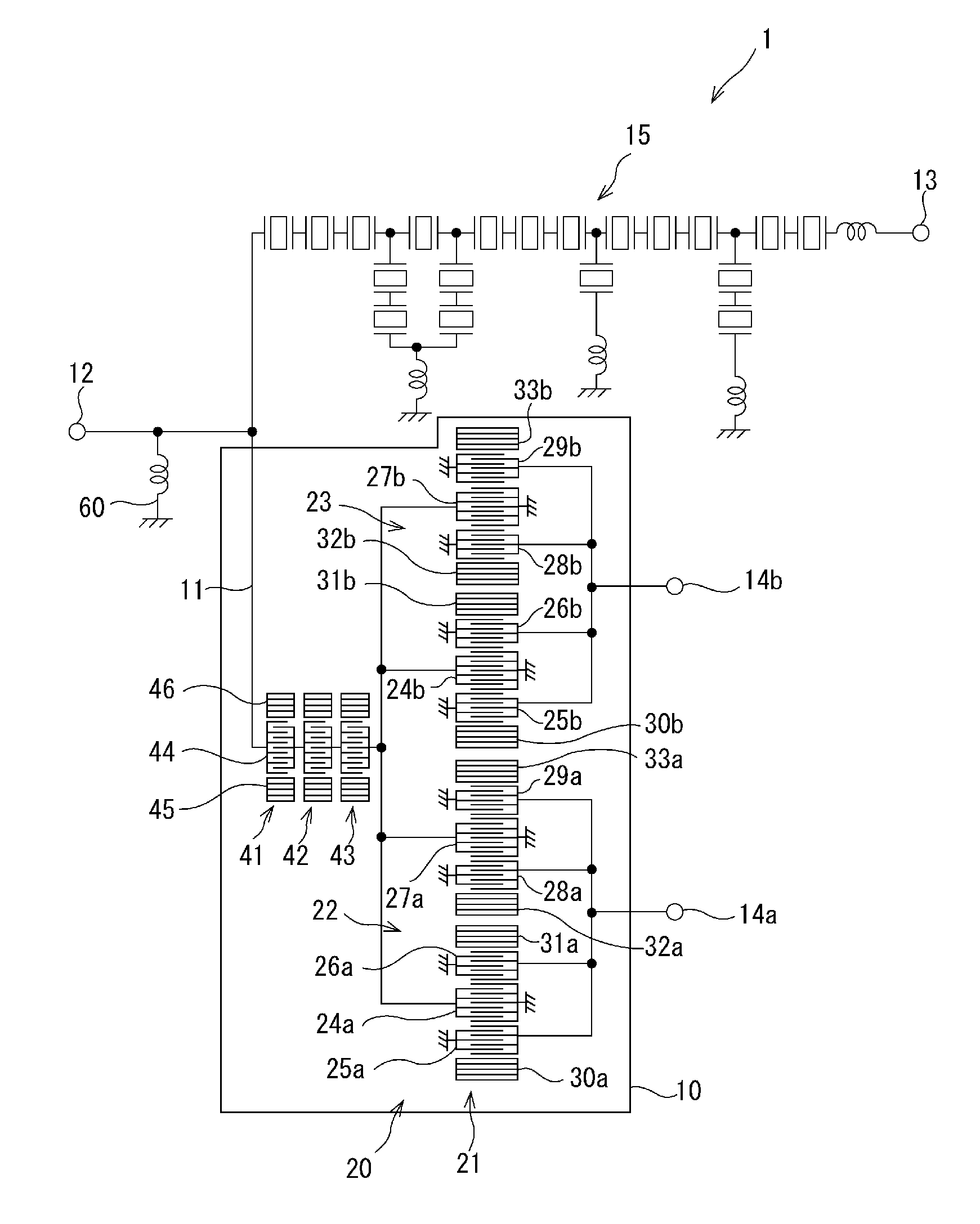
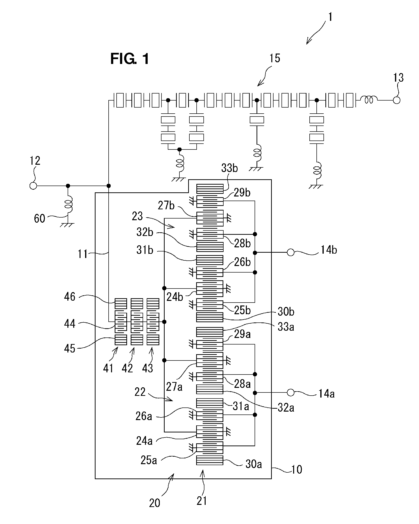
[0040]A surface acoustic wave branching filter similar in configuration to the surface acoustic wave duplexer 1 described in the above-described preferred embodiment was produced as Preferred Embodiment Example 1 with the following design parameters.

Longitudinally coupled resonator-type surface acoustic wave filter unit 22:

[0041]Intersecting width: 46 μm

[0042]Number of electrode fingers of IDT electrodes 25a and 26a: 28 (wherein number of electrode fingers of narrow-pitch electrode finger portions is 8)

[0043]Number of electrode fingers of IDT electrode 24a: 71 (wherein number of electrode fingers of narrow-pitch electrode finger portion on the side of IDT electrode 25a is 4, and number of electrode fingers of narrow-pitch electrode finger portion on the side of IDT electrode 26a is 4)

[0044]Number of electrode fingers of reflectors 30a and 31a:

[0045]Duty ratio of IDT electrodes 24a, 25a, and 26a: 0.64

[0046]Electrode film thickness: 0.091λI (wherein λI r...

embodiment example 2

Preferred Embodiment Example 2

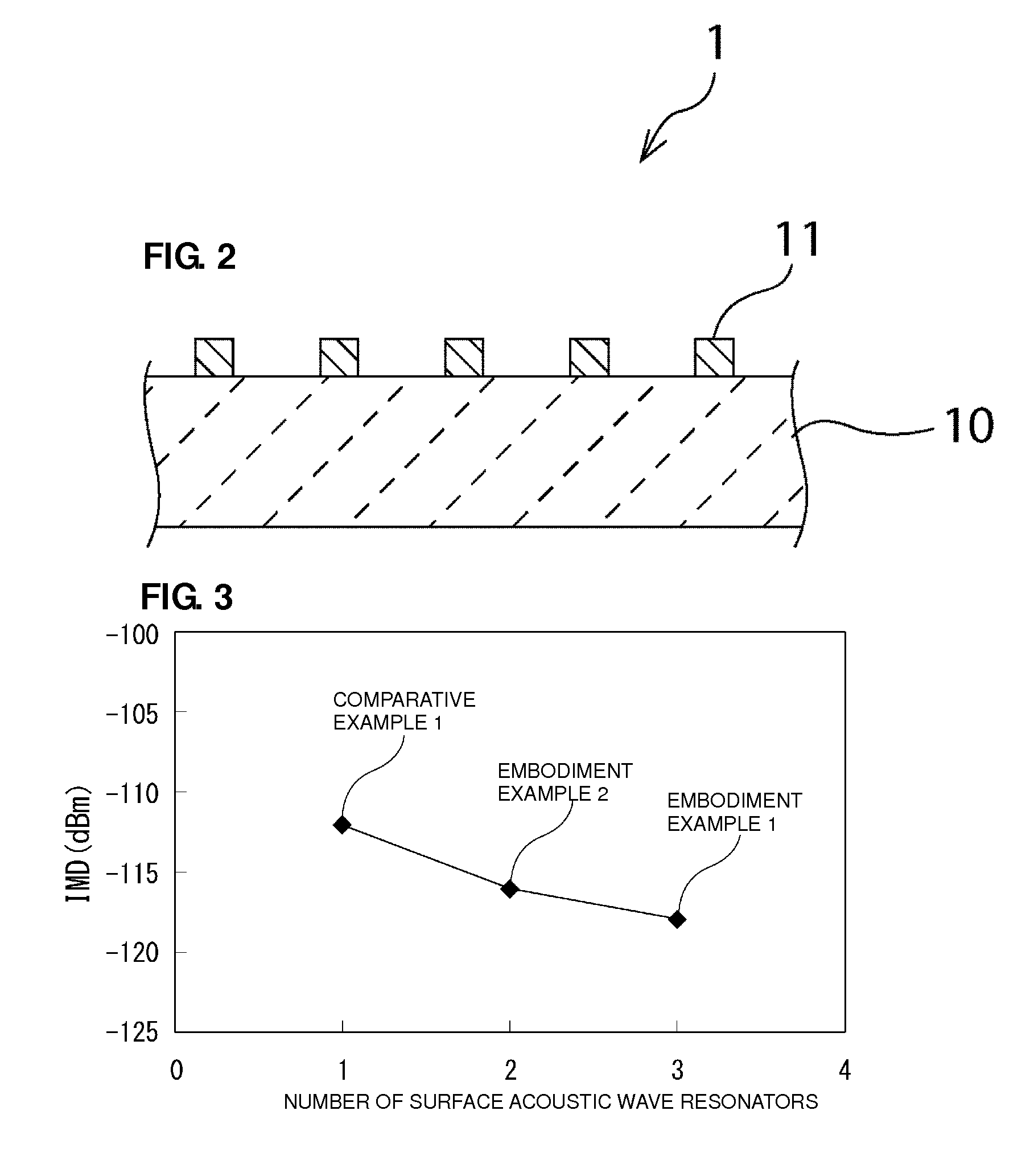
[0059]The number of surface acoustic wave resonators connected in series between the antenna terminal 12 and the reception filter 20 was set to two, and the intersecting width and the number of pairs of electrode fingers were set such that the combined capacitance of the two surface acoustic wave resonators is the same as the combined capacitance C1 of the surface acoustic wave resonators 41 to 43 of Preferred Embodiment Example 1. Specifically, the present preferred embodiment example was configured to be similar to the above-described preferred embodiment Example 1 except for the following design parameters.

[0060]First and second surface acoustic wave resonators:

[0061]Intersecting width of IDT electrodes: 21.2 μm Number of electrode fingers of IDT electrodes: 201

first modified example

[0080]FIG. 7 is a schematic cross-sectional view of a portion of a boundary acoustic wave branching filter according to a first modified example of a preferred embodiment of the present invention.

[0081]In the above-described preferred embodiment, description has been made of a preferred embodiment of the present invention with reference to, as an example, the surface acoustic wave duplexer 1 including the reception filter 20 that preferably is the longitudinally coupled resonator-type surface acoustic wave filter 21 using the surface acoustic wave. An elastic wave branching filter according to the present invention, however, is not limited to the surface acoustic wave branching filter. For example, an elastic wave branching filter according to the present invention may be a boundary acoustic wave branching filter using boundary acoustic wave, in which first and second dielectric layers 50 and 51 are arranged on the piezoelectric substrate 10 to cover the electrodes 11, as illustrate...


PUM


Abstract

An elastic wave surface acoustic wave duplexer includes an antenna terminal, a transmission filter, a reception filter, and a plurality of elastic wave resonators connected in series between the antenna terminal and the reception filter. The reception filter is a longitudinally coupled resonator-type surface acoustic wave filter including a plurality of IDT electrodes and arranged along a propagation direction of elastic wave. A combined capacitance of the plurality of surface acoustic wave resonators is smaller than a capacitance of the IDT electrodes and included in the plurality of IDT electrodes and connected to the antenna terminal.

Description

BACKGROUND OF THE INVENTION[0001]1. Field of the Invention[0002]The present invention relates to an elastic wave branching filter.[0003]2. Description of the Related Art[0004]In recent years, elastic wave branching filters using elastic waves, such as surface acoustic waves and boundary acoustic waves, have been widely used in communication devices, such cellular phones. For example, Japanese Unexamined Patent Application Publication No. 2008-5151 discloses a surface acoustic wave branching filter illustrated in FIG. 8.[0005]As illustrated in FIG. 8, a surface acoustic wave branching filter 100 includes a transmission filter 104 connected between an antenna terminal 101 and a transmitting terminal 102 and a reception filter 105 connected between the antenna terminal 101 and receiving terminals 103a and 103b. In the surface acoustic wave branching filter 100, the reception filter 105 is formed by a longitudinally coupled resonator-type surface acoustic wave filter. A surface acoustic...

Claims


Application Information

Patent Timeline
Patent Type & Authority Patents(United States)
IPC IPC(8): H03H9/72H03H9/64H03H7/42H03H7/46H03H9/00H03H9/02H03H9/145
CPCH03H7/461H03H9/0085H03H9/6483H03H9/6496H03H9/725H03H7/42H03H9/008H03H9/02748H03H9/02929H03H9/14579
Inventor TAKAMINE, YUICHI
Owner MURATA MFG CO LTD
Why Eureka
Try Eureka