Liquid ejection apparatus
a technology of liquid ejection and pump, which is applied in the direction of printing and inking apparatus, etc., can solve the problems of insufficient damper removal and large pressure variation, and achieve the effect of efficient liquid supply, effective elimination of pulsating action of pumps, and accurate control
- Summary
- Abstract
- Description
- Claims
- Application Information
AI Technical Summary
Benefits of technology
Problems solved by technology
Method used
Image
Examples
first embodiment
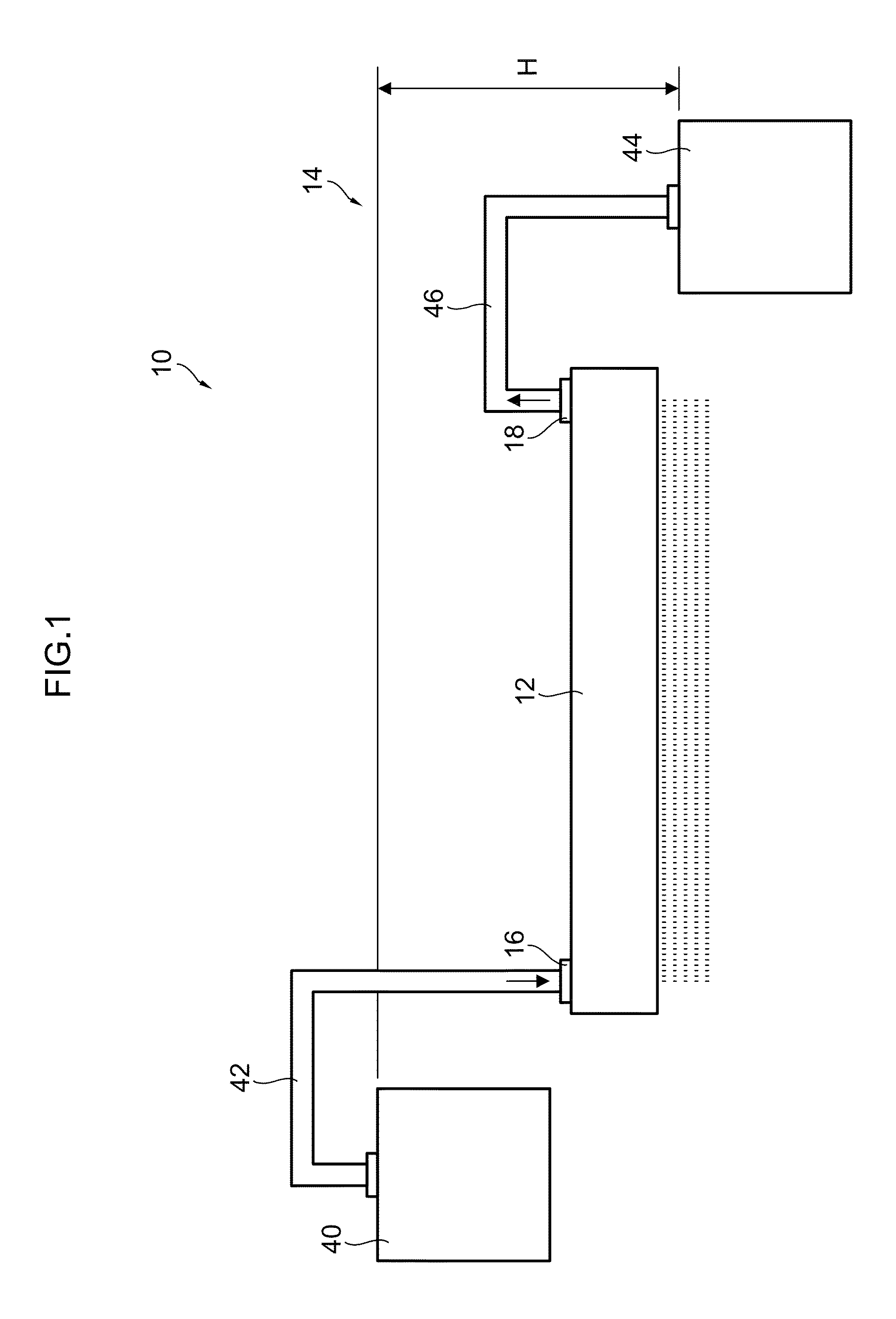
[0070]FIG. 1 is a schematic drawing of a liquid ejection apparatus 10 according to a first embodiment of the present invention.
[0071]As shown in FIG. 1, the liquid ejection apparatus 10 includes a liquid ejection head 12 (hereinafter referred simply as the “head”12) configured to eject droplets of liquid, and a liquid supply and recovery unit 14 configured to supply and recovery the liquid to and from the head 12.
[0072]
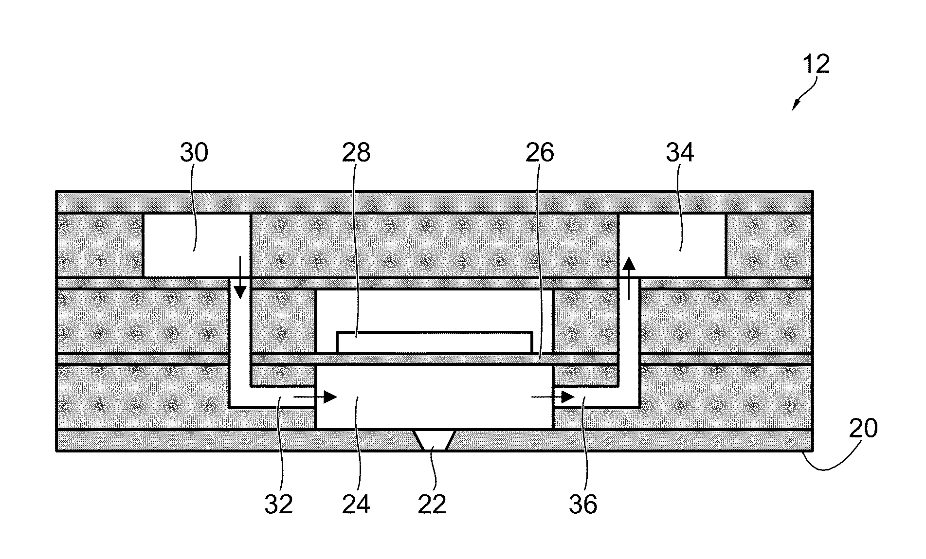
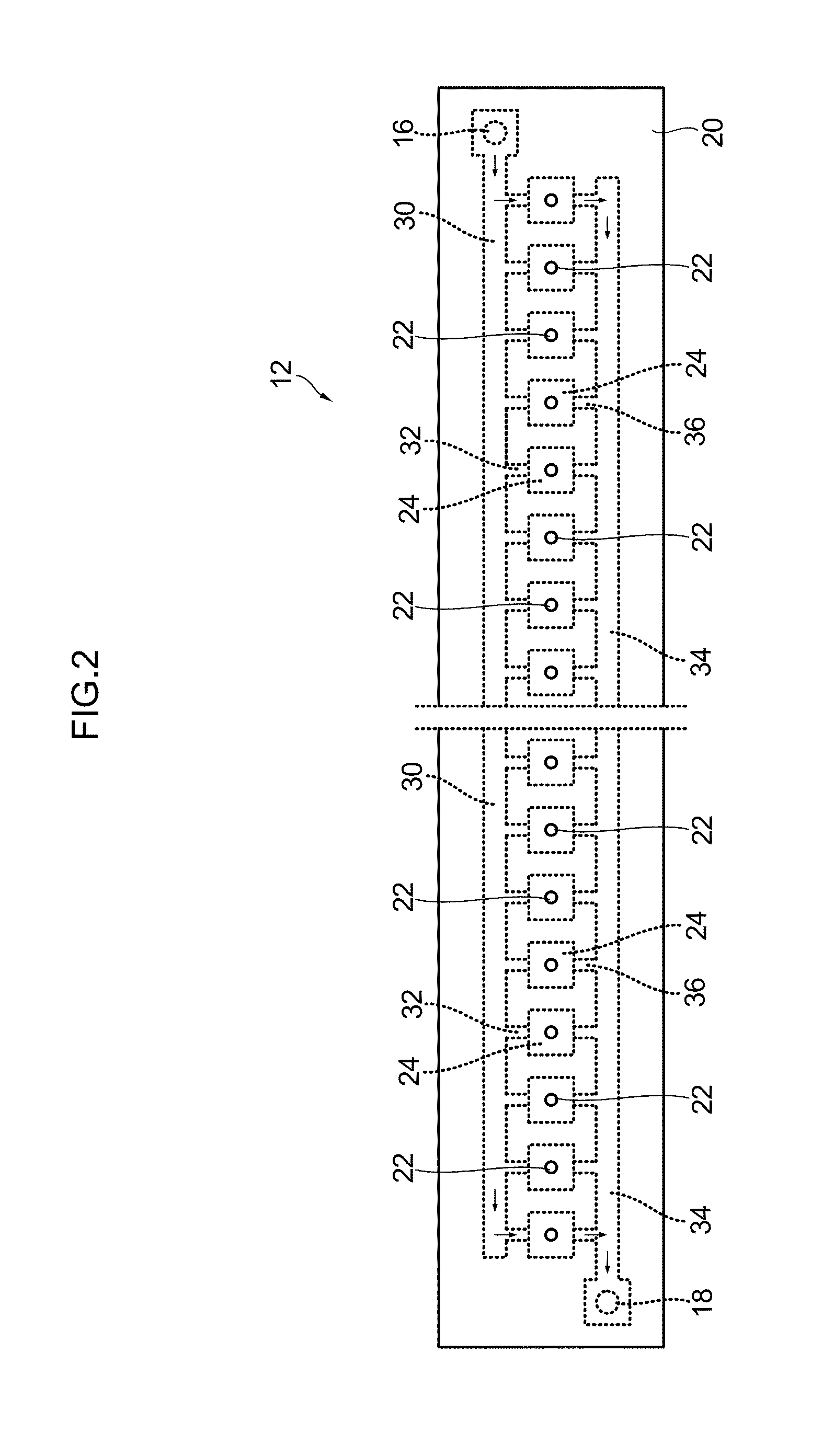
[0073]The head 12 is a so-called circulation head, which is provided with a supply port 16 and a recovery port 18 for the liquid. The liquid is continuously supplied to the head 12 though the supply port 16 and is continuously recovered from the head 12 through the recovery port 18. Consequently, a flow of the liquid from the support port 16 toward the recovery port 18 is formed inside the head 12, and it is thereby possible to prevent the liquid inside the head 12 from keeping bubbles or increasing in the viscosity.
[0074]The head 12 is formed in a rectangular block s...
second embodiment
[0130]FIG. 5 is a schematic drawing of a liquid ejection apparatus 10A according to a second embodiment of the present invention.
[0131]As shown in FIG. 5, the liquid ejection apparatus 10A according to the present embodiment carries out the supply and recovery of the liquid by means of pumps. The composition of the head 12 is the same as the liquid ejection apparatus 10 according to the first embodiment described above, and therefore only the composition of the liquid supply and recovery unit 14 for carrying out the supply and recovery of the liquid to and from the head 12 is described here.
[0132]
[0133]As shown in FIG. 5, the liquid supply and recovery unit 14 includes: a supply tank 40; a supply tube 42; a recovery tank 44; a recovery tube 46; a supply pump 48, which conveys the liquid contained in the supply tank 40 to the head 12 through the supply tube 42; a supply damper 50, which is arranged in the supply tube 42; a recovery pump 52, which conveys the liquid from the head 12 t...
third embodiment
[0154]FIG. 6 is a schematic drawing of a liquid ejection apparatus 100 according to a third embodiment of the present invention.
[0155]As shown in FIG. 6, in the liquid ejection apparatus 100 according to the present embodiment, a liquid ejection head 112h is constituted by joining together a plurality of head modules 112m. The liquid is independently supplied to and recovered from each head module 112m, by the liquid supply and recovery unit 114.
[0156]
[0157]As described above, the head 112h according to the present embodiment is constituted by joining together the plurality of head modules 112m.
[0158]The head modules 112m have the same structure. Furthermore, the basic structure of each head module 112m is the same as the head 12 according to the first embodiment described above. More specifically, each of the head modules 112m is provided with a supply port 116 and a recovery port 118, and the liquid is supplied continuously to the supply port 116 and is also recovered continuousl...
PUM
 Abstract
Description
Claims
Application Information
 - R&D
- Intellectual Property
- Life Sciences
- Materials
- Tech Scout
- Unparalleled Data Quality
- Higher Quality Content
- 60% Fewer Hallucinations
Browse by: Latest US Patents, China's latest patents, Technical Efficacy Thesaurus, Application Domain, Technology Topic, Popular Technical Reports.
© 2025 PatSnap. All rights reserved.Legal|Privacy policy|Modern Slavery Act Transparency Statement|Sitemap|About US| Contact US: help@patsnap.com


