Switching Element, Power Converter, Direct Current Transmission System, Current Control Device, Method of Controlling Power Converter, and Method of Controlling Current in Voltage Source Converter

a technology of power converter and current control device, which is applied in the direction of ac-ac conversion, dc-ac conversion without reversal, ac-ac conversion, etc., can solve the problems of insufficient flowing current, large loss of resistor, and insufficient supply of power

Active Publication Date: 2013-08-15
HITACHI LTD
View PDF2 Cites 61 Cited by
  • Summary
  • Abstract
  • Description
  • Claims
  • Application Information

AI Technical Summary

Problems solved by technology

However, according to the technology disclosed by Patent Document 1, as a low voltage is formed by dividing a capacitor voltage, which is a high voltage, by resistors, there is a problem that loss by the resistors becomes large.
However, in the power converter, in case that a deviation from a normal operation has occurred (for example, a light load state) in driving the respective switching elements such that power conversion is performed between an alternate current output section and a direct current output section, this flowing current is insufficient.
Consequently, power cannot be sufficiently supplied with one of electrical elements related to this current as an energy source, and accordingly, the respective switching elements cannot drive themselves.

Method used


Image

  • Switching Element, Power Converter, Direct Current Transmission System, Current Control Device, Method of Controlling Power Converter, and Method of Controlling Current in Voltage Source Converter
  • Switching Element, Power Converter, Direct Current Transmission System, Current Control Device, Method of Controlling Power Converter, and Method of Controlling Current in Voltage Source Converter
  • Switching Element, Power Converter, Direct Current Transmission System, Current Control Device, Method of Controlling Power Converter, and Method of Controlling Current in Voltage Source Converter

Examples


first embodiment

Advantages of First Embodiment

[0313]The foregoing first embodiment has advantages as the following (A) to (E).

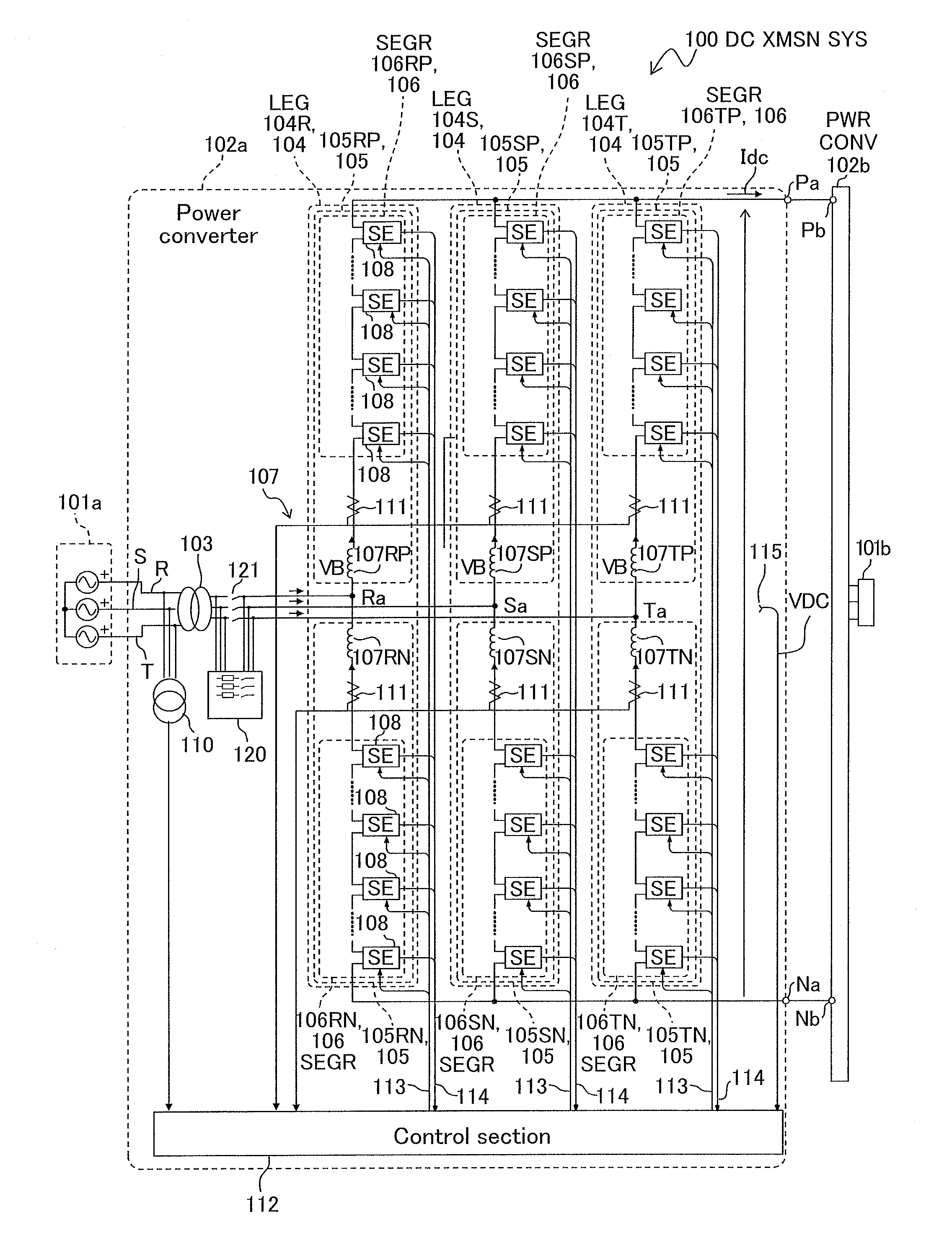
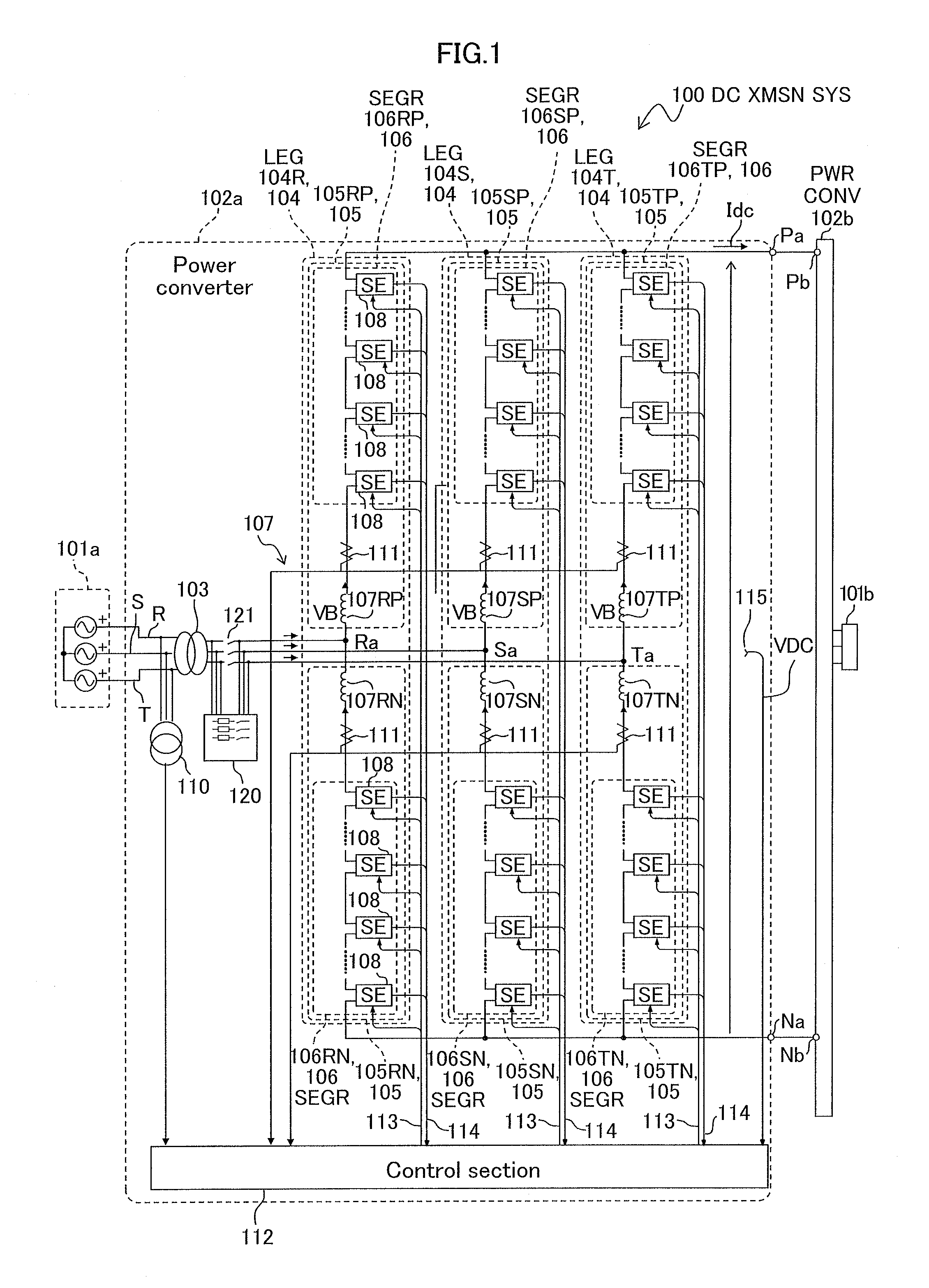
(A) The circuit for supplying current from the voltage applied to the capacitor 203 of a bi-directional chopper switching element 108 divides a DC voltage of several thousand volts into low voltages by the resistors R2 and R3. Accordingly, a power loss is generated by the resistor R2. Particularly, in a case of supplying a power of several watts, the power loss due to the resistor R2 becomes significant. In the first embodiment, a bi-directional chopper switching element 108 is capable of supplying power to the gate driver 205 through the current transformer 207 during operation of the power converter 102a. Thus, a power loss due to the resistor R2 can be reduced.

(B) A bi-directional chopper switching element 108 is configured such that the current transformer 207, which is power obtaining means, is serially connected to the capacitor 203, and a current flowing on the second...

second embodiment

Advantages of Second Embodiment

[0350]The foregoing second embodiment has advantages as the following (F) and (G).

(F) The q-axis second harmonic components of the circulating current IRb, ISb, and ITb have a frequency different from the frequency of the grid currents IR, IS, and IT. Accordingly, these q-axis second harmonic components can be easily controlled so as to make the circulating currents IRb, ISb, and ITb be at a desired level. Thus, a bi-directional chopper switching element 108 is capable of stably supplying a power source to itself from a current flowing in the current transformer 207 of the self-supply power source 206.

(G) The control section 112a in the second embodiment detects the second harmonic amplitudes of capacitor voltage VC by the second-harmonic-amplitude detector 316, detects the minimum value of the detected second harmonic amplitudes by the minimum value computing unit 317, and performs feedback control so that this minimum value converges to a predetermin...

third embodiment

Advantage of Third Embodiment

[0460]The foregoing third embodiment has an advantage in the following (H).

(H) As a reactor is unnecessary for the power converters 102c and 102d of the direct current transmission system 100b, the volume and the weight can be reduced, in addition to the advantages similar to those of the power converters 102a and 102b in the first and second embodiments.

(Configuration in Fourth Embodiment)

[0461]FIG. 29 is a schematic configuration diagram showing a direct current transmission system 100c in a fourth embodiment. The same reference symbols are assigned to the same elements as those of the direct current transmission system 100b in the third embodiment shown in FIG. 22.

[0462]The direct current transmission system 100c in the fourth embodiment is provided with a control device 150c that is different from the control device 150 (see FIG. 22) in the third embodiment. The control device 150c in the fourth embodiment is provided with a DC current regulating sec...


PUM


Abstract

A switching element of a power converter generates a low voltage, using a current flowing in the power converter, and supplies a power to drive itself. A switching element of a power converter for conversion from direct current into alternate current or from alternate current into direct current includes: a terminal and a terminal which are used in building the switching element itself in the power converter; a capacitor, a high-side controllable switch and a low-side controllable switch enabling outputting the voltage of the capacitor, the voltage being output between the terminal and the terminal, and a self-supply power source for supplying a power to drive the bi-directional chopper switching element itself, using a current flowing in the capacitor.

Description

CROSS REFERENCE TO RELATED APPLICATION[0001]This application claims the foreign priority benefit under Title 35, United States Code, §119(a)-(d) of Japanese Patent Application No. 2012-025679, filed on Feb. 9, 2012 in the Japan Patent Office, Japanese Patent Application No. 2012-064181, filed on Mar. 21, 2012 in the Japan Patent Office, and Japanese Patent Application No. 2012-261892, filed on Nov. 30, 2012 in the Japan Patent Office, the disclosures of which are herein incorporated by reference in their entirety.TECHNICAL FIELD[0002]The present invention relates to a switching element provided with a semiconductor controllable switch, a capacitor, and an internal power source circuit, a voltage source converter configured by serially connecting a plurality of such switching elements, a direct current transmission system, a current control device, a method of controlling a power converter, and a method of controlling the current of a voltage source converter.BACKGROUND ART[0003]In r...

Claims


Application Information

Patent Timeline
Patent Type & Authority Applications(United States)
IPC IPC(8): H02M7/12H02M7/48
CPCH02M7/12H02M7/48H02M2007/4835H02M7/483H02M7/217H02M1/08H02M1/0006H02M7/4835
Inventor YAMAMOTO, TAKAYOSHIICHINOSE, MASAYABANDO, AKIRAYAMASHITA, KEIICHIINOUE, SHIGENORIYOSHIHARA, TORUEGUCHI, YOSHIOSAKUCHI, OSAMUKATOH, SHUJIITO, TOMOMICHI
Owner HITACHI LTD
Why Eureka
Try Eureka