Vehicle with a multilayer roof structure and a microphone unit integrated into the roof structure

a multi-layer roof and roof structure technology, applied in vehicle components, electrical transducers, transducer details, etc., can solve the problem of high insensitivity, and achieve the effect of facilitating its handling during installation and no interference nois

Active Publication Date: 2013-08-15
PEIKER ACUSTIC GMBH & CO KG
View PDF4 Cites 11 Cited by
  • Summary
  • Abstract
  • Description
  • Claims
  • Application Information

AI Technical Summary

Benefits of technology

[0007]According to the invention, it is provided that the microphone unit is arranged partially or completely in the through opening of the supporting layer. As a result of this, the installation of a microphone unit is possible without problems, even in vehicles with a thin roof structure.
[0008]According to the invention, the microphone unit comprises, in addition to the microphone mentioned above, a housing and in particular a preamplifier. Here, one side of the housing forms the sound entry region and the microphone unit also comprises in particular a holder for fixing the microphone unit and in particular the housing of the microphone unit. Such a design of the microphone unit facilitates its handling during installation, because the housing, which comprises at least the microphone, can be integrated into the roof structure using the holder with few working steps.
[0009]According to the invention, the holder comprises a shaft, in which the housing of the microphone unit is arranged in the shaft, and the holder also comprises at least one attachment vane arranged on the shaft, wherein in particular the attachment vane lies in a plane in relation to a longitudinal axis of the shaft, which plane is intersected orthogonally by the longitudinal axis, wherein the attachment vane encircles the shaft, especially annularly, wherein an underside of the attachment vane forms a first contact surface, wherein an upper side of the attachment vane forms a second contact surface and wherein the shaft of the holder especially protrudes through the opening in the supporting layer in the mounted state. By a suitable design, the holder forms an adapter, by means of which the housing can be optimally integrated into the roof structure without the housing having to have a special design for this purpose.
[0010]With the holder in the assembled state, the invention provides that the holder rests with the first contact surface on a mating contact surface, which faces the upper covering layer, the mating contact surface being part of the supporting layer of the roof structure. Here the contact surface and the mating contact surface are in particular glued together. As a result of this, the holder or the microphone unit is mounted in the roof structure so as to be vibration-proof and it is ensured that the holder cannot vibrate relative to the roof structure and thus in addition no interference noise can be produced by the holder.
[0011]According to the invention, it is also provided that the roof structure of the vehicle is equipped with an intermediate layer, wherein the intermediate layer is arranged between the supporting layer and the upper covering layer and contacts the supporting layer, wherein the intermediate layer has a recess, in particular facing towards the supporting layer, which is oriented towards the through opening of the supporting layer, wherein the holder is mounted with its attachment vane between the supporting layer and the intermediate layer and contacts the mating contact surface of the supporting layer with the first contact surface of its attachment vane and contacts a mating contact surface of the intermediate layer with the second contact surface of its attachment vane, wherein the holder is optionally clamped with its attachment vane between the supporting layer and the intermediate layer or is glued or clamped to at least one of the layers and glued to at least one layer and wherein the shaft of the holder when in the mounted state especially protrudes into the recess of the intermediate layer. As a result of this, secure fixing of the microphone unit in the roof structure of the vehicle is guaranteed for a roof structure with an intermediate layer.
[0013]The invention provides a separation of at least 1 mm between the sound entry region of the microphone unit and the lower covering layer, wherein a cavity is formed between the microphone unit and the lower covering layer in the roof structure. As a result of this, the microphone unit does not form an impression on the covering layer that can be seen from the interior of the vehicle. Furthermore, this enables reliable decoupling to be achieved between the microphone and the lower covering layer, because no component of the microphone assembly is in direct contact with the lower covering layer.

Problems solved by technology

As a result of this, the microphone unit is not only arranged discreetly and unobtrusively without the use of additional components, but it has—by the use of the lower covering layer as a filter—a high level of insensitivity to wind noise.

Method used


Image

  • Vehicle with a multilayer roof structure and a microphone unit integrated into the roof structure
  • Vehicle with a multilayer roof structure and a microphone unit integrated into the roof structure
  • Vehicle with a multilayer roof structure and a microphone unit integrated into the roof structure

Examples


Embodiment Construction

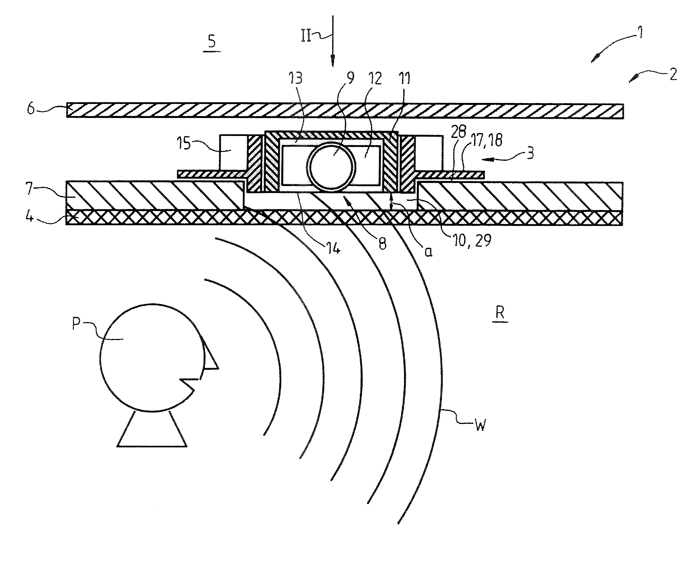
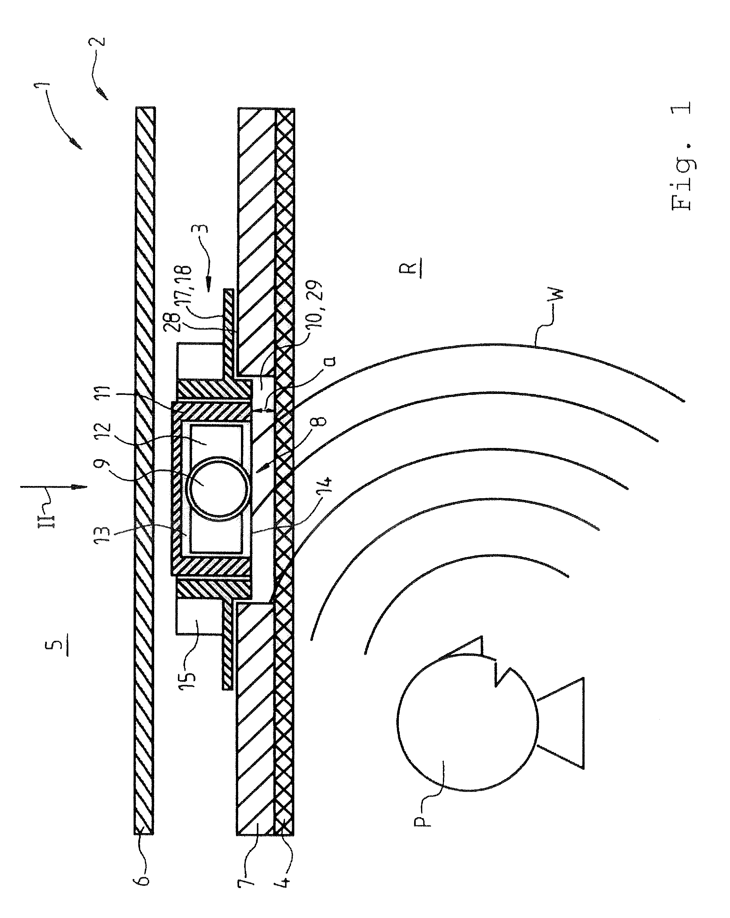
[0027]In FIG. 1, a schematic view of a sectional lateral view of a portion of a motor vehicle 1 is shown. The motor vehicle 1 comprises a multilayer roof structure 2, wherein a microphone unit 3 is integrated into the roof structure 2. The roof structure 2 comprises a lower covering layer 4 that is visible from an interior space R of the vehicle, an upper covering layer 6 delimiting the motor vehicle 1 relative to the surroundings 5, and a supporting layer 7. Here the supporting layer 7 is arranged between the lower covering layer 4 and the upper covering layer 6. The lower covering layer 4 is joined to the supporting layer 7. The microphone unit 3 arranged in the roof structure 2 comprises a sound entry region 8 and a microphone 9. For receiving the microphone unit 3 into the roof structure 2, the supporting layer 7 has a through opening 10, wherein the through opening 10 reaches to the lower covering layer 4. The through opening 10 is closed to the interior of the vehicle R by the...


PUM


Abstract

The invention relates to a vehicle having a multilayer roof structure and a microphone unit integrated into the roof structure. Here, a supporting layer has a through opening reaching to a lower covering layer, wherein the through opening is covered by the lower covering layer, wherein the microphone unit is associated with the through opening and wherein the microphone unit is opposite the lower covering layer with its sound entry region.

Description

CROSS REFERENCE TO RELATED APPLICATIONS[0001]This application claims the benefit under 35 USC §119(e) of U.S. Provisional Application 61 / 596,840, filed Feb. 9, 2012, and claims the benefit under 35 USC §119(a)-(d) of German Application No. 10 2012 002 414.2 filed Feb. 9, 2012, the entireties of which are incorporated herein by reference.FIELD OF THE INVENTION[0002]The invention relates to a vehicle with a multilayer roof structure and a microphone unit integrated into the roof structure.BACKGROUND OF THE INVENTION[0003]A vehicle is known from DE 10 2004 019 827 A1, which comprises a multilayer roof structure and a microphone unit integrated into the roof structure, wherein the roof structure comprises a lower covering layer visible from a vehicle interior space, an upper covering layer delimiting the vehicle relative to the surroundings, a supporting layer carrying the lower covering layer and lying between the lower and the upper covering layers, and wherein the microphone unit com...

Claims


Application Information

Patent Timeline
Patent Type & Authority Applications(United States)
IPC IPC(8): H04R1/02
CPCH04R1/028H04R1/086B60R2011/0028B60R11/0247H04R2499/13
Inventor HOOK BRANDON
Owner PEIKER ACUSTIC GMBH & CO KG
Why Eureka
Try Eureka