Adjustable clamping device

a clamping device and adjustable technology, applied in the direction of snap fasteners, buckles, mechanical devices, etc., can solve the problems of easy gas or liquid leakage, worse clamping performance, etc., and achieve excellent closing effects and avoid disengagement of the clamping device from the multi-port valve

Inactive Publication Date: 2013-08-22
CHEN JUN FAN
View PDF13 Cites 10 Cited by
  • Summary
  • Abstract
  • Description
  • Claims
  • Application Information

AI Technical Summary

Benefits of technology

[0019]Since the jaw opening of the adjustable clamping device is adjustable in breadth, it is suitable for various kinds of multiport valves, the first

Problems solved by technology

The resistance of the plug to the gas or liquid pressure is usually insufficient, and thus the plug will be pushed outwardly by degrees such that the gas or liquid can leak.
However, the two jaws of the conventional clamping device are formed with respective flat clamping surfaces, thus resulting in a worse clamping performance so

Method used


Image

  • Adjustable clamping device
  • Adjustable clamping device
  • Adjustable clamping device

Examples


Embodiment Construction

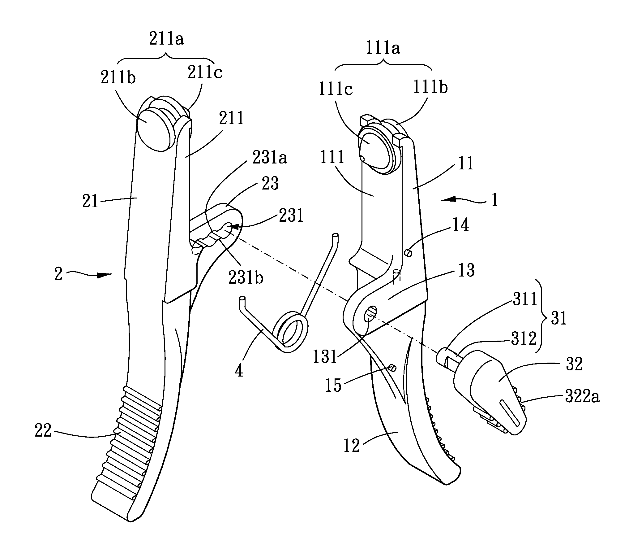
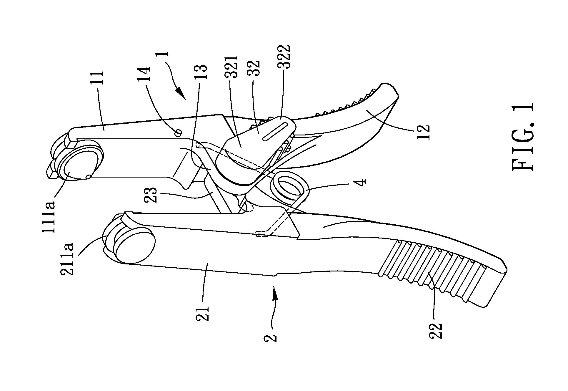
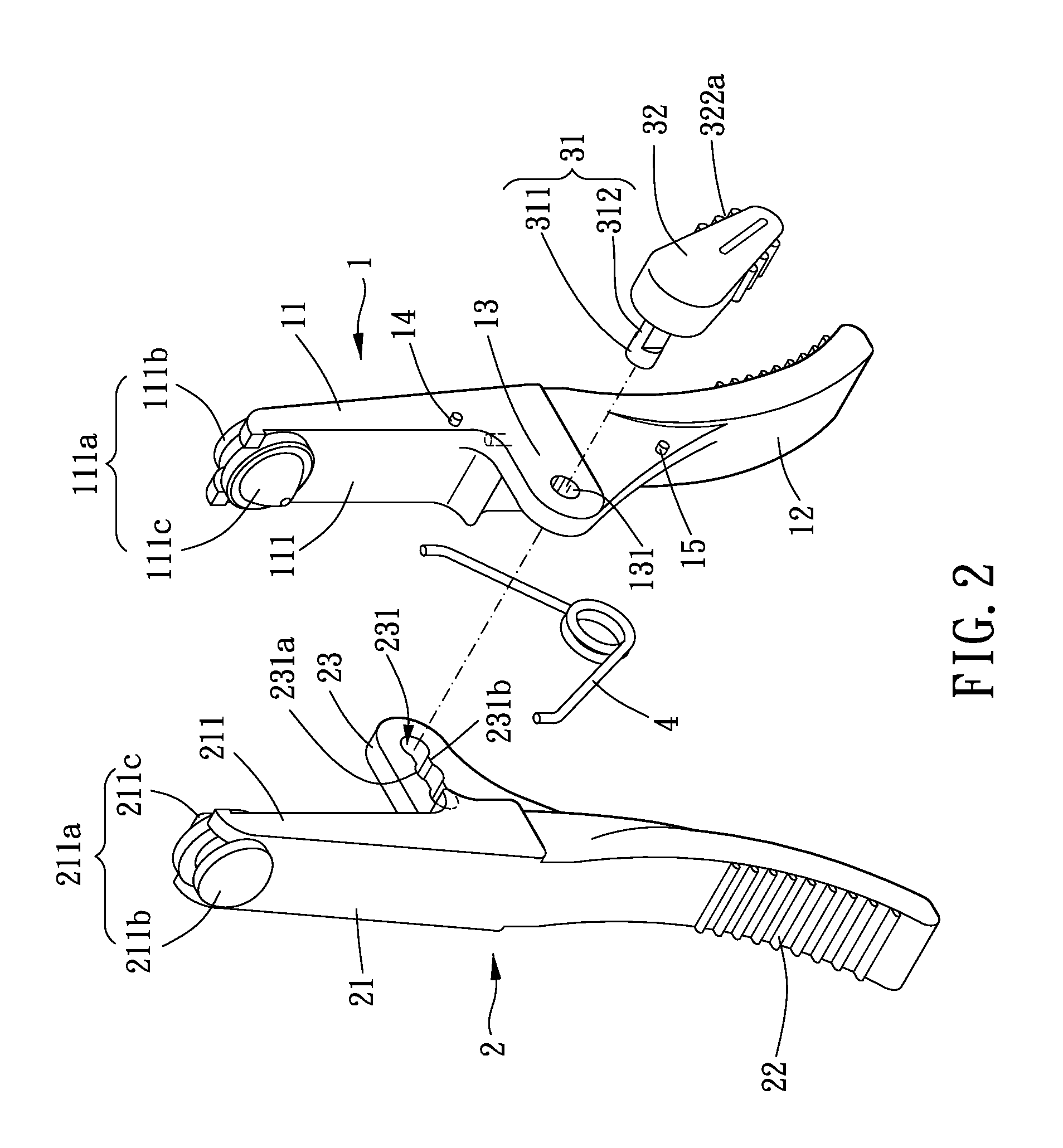
[0028]As shown in FIGS. 1 and 2, an adjustable clamping device of the present invention includes a first clamping body 1, a second clamping body 2, an adjusting mechanism and an elastic member 4.

[0029]The first clamping body 1 includes a first jaw 11, a first handle 12, a first connecting portion 13, an unlocking portion14 and a locking portion 15.

[0030]The first jaw 11 extends from one end of the first handle 12 in a longitudinal direction of the first handle 12 so that the first clamping body 1 is elongated. In addition, the first jaw 11 has a first clamping surface 111 formed with a slot and a first blocking member 111a. The first blocking member 111a includes a positioning portion 111b and a plug 111c, and the plug 111 extends from the top of the positioning portion 111b and is cone-shaped. The positioning portion 111b is detachably disposed in the slot, and the plug 111c faces toward the second clamping body 2.

[0031]The first connecting portion 13 extends from an interconnectio...


PUM


Abstract

An adjustable clamping device is provided. The device includes a first and a second clamping body, an adjusting mechanism and an elastic member. The first clamping body includes a first jaw formed with a first locking member and a first connecting portion formed with first limiting portion. The second clamping body includes a second jaw formed with second blocking member and a second connecting portion formed with at least two second limiting portions. A jaw opening is formed between the first and second jaws. The adjusting mechanism includes a shaft which is rotatably positioned at the first limiting portion and selectively positioned at one of the second limiting portions.

Description

BACKGROUND OF THE INVENTION[0001]1. Field of the Invention[0002]The present invention relates to an adjustable clamping device.[0003]2. Description of the Prior Art[0004]A multiport valve is used mainly to connect a primary pipe and manifold pipes, so as to decrease the amount of the pipes mounted between two devices.[0005]When some of the openings of the multiport valve should be somehow temporarily closed, a conventional plug is usually used to close the openings to be closed, and other openings of the multiport valve are still connected to the pipes and can allow the gas or liquid in the primary pipe to flow into the device to which the pipes are connected. However, the gas or liquid could generate pressure, and the plug resists the gas or liquid pressure by means of the friction between the plug and the pipe of the multiport valve. The resistance of the plug to the gas or liquid pressure is usually insufficient, and thus the plug will be pushed outwardly by degrees such that the...

Claims


Application Information

Patent Timeline
IPC IPC(8): F16B2/02
CPCF16B2/10Y10T24/44427F16K43/00
Inventor CHEN, JUN FAN
Owner CHEN JUN FAN
Why Eureka
Try Eureka