Eureka AIR delivers breakthrough ideas for toughest innovation challenges, trusted by R&D personnel around the world.

Heat Pump

Inactive Publication Date: 2013-08-22
PLANET INTPROP ENTERPRISES
View PDF0 Cites 6 Cited by
  • Summary
  • Abstract
  • Description
  • Claims
  • Application Information

AI Technical Summary

Benefits of technology

The invention is a system for extracting heat from a roof cavity and delivering it to a home through a ducting system. The fan is placed close to the evaporator, which is located at the top of the tank. This design reduces the need for complicated plumbing lines and ensures the components of the system are stable. The system is simple and cost-effective to install.

Problems solved by technology

There are however a number of key limitations associated with heat pumps.
Despite being a relatively efficient source of heat exchange they still consume a significant amount of energy.
The efficiency of the Heat Pump reduces as the air source temperature drops.
Current commercial air source heat pumps become unviable as the air temperature approaches zero.
Once the evaporator is choked by ice it can no longer function and the heat pump efficiency will drop to near zero.
Unfortunately, this may provide a worst case operating scenario for a heat pump.
Even though the advertised COP of a heat pump may be between 3 and 5, on a cold night the typical observed performance is likely to drop below 2 and where icing occurs the total cycle COP may drop below 1 resulting in performance that is even worse than the electric element heater is was designed to replace.
An additional and independent issue related to heat pumps is that they emit compressor and fan noise.
Heat pumps are typically located outside and this noise can adversely impact on home owners and their neighbours, particularly in high density living arrangements.
A significant part of this problem is the time when the heat pump operates—typically associated with peak hot water usage being either in the morning or in the evening.
Both of these times can cause problems.
For example, if a person showers in the evening a heat pump may kick in and run for 3 or more hours, making noise at a time when residents may be attempting to go to sleep.
However, such prior art solutions only allow for management of time of operation, it has no knowledge of how much hot water is in the tank, the users typical or current consumption patterns, air source temperature, electricity tariffs etc.
Furthermore, using such prior art systems, it is possible for the user to run out of hot water.
Moreover, such prior art systems determine a preset daily heating regime and do NOT allow for any dynamic decision making.
There are currently no heat pumps on the market that offer this level of flexibility.
This type of system is very expensive to install and is most suited to cold climates where geothermal heat energy is readily available.
These are not switchable or selective systems but rely on a renewable source of geothermal energy to maintain the evaporator temperature.
Another alternative to the air source heat pump is the solar assisted heat pump where the evaporator is integrated to a solar thermal panel typically mounted on the roof This type of system provides excellent performance when the sun is shining but operation is very inefficient on cold nights and is therefore not suited to off-peak operation.
Previously the high cost, low reliability and low efficiency of heat pumps has precluded them from competing against conventional electric water heaters and gas water heaters.
This provides excellent daytime performance but is unsuitable for off-peak night time operation;4. Retrieve the heat from a “renewable” source such as the ground.
This is very expensive, only suitable for some geographic areas and falls outside the realm of air sourced heat pumps.
However, notwithstanding the current developments, none of the available heat pump systems provide a configuration combining ease of installation and access to optimal input air supplies.
In a typical domestic situation the time that the heat pump runs is not well aligned with when the heat pump should run to minimise either energy use or energy costs.
When a heat pump will consume more energy and in cold climates could cost more to run than if operating outside the off-peak interval.
These prior art devices are typically used to load-shed during peak consumption (and therefore tariff) intervals and have no knowledge of water consumption or tank capacity and therefore cut the power independent of the need to reheat the water storage.

Method used


Image

  • Heat Pump
  • Heat Pump
  • Heat Pump

Examples


example one

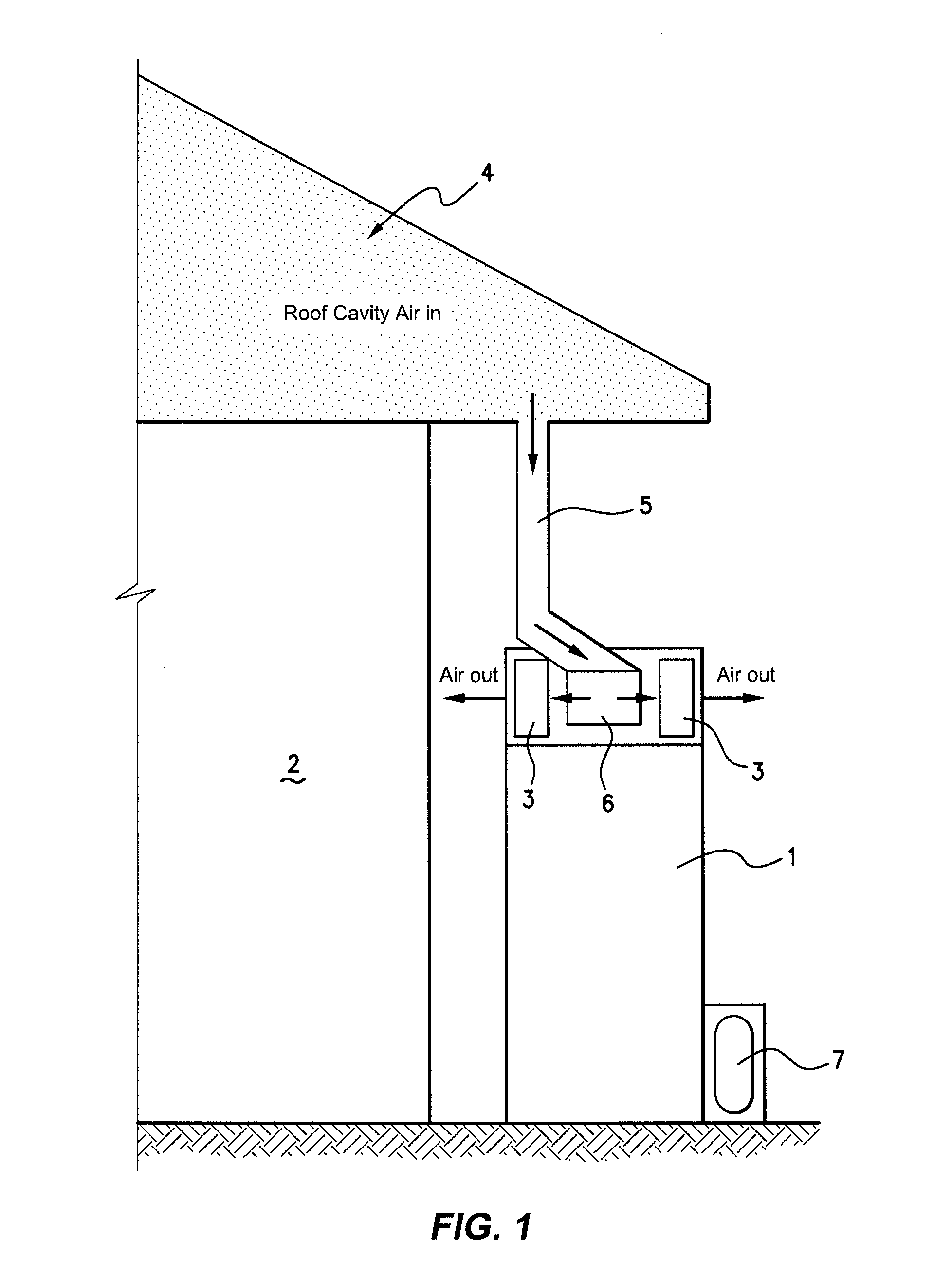
[0067]Referring firstly to FIG. 1, a particularly preferred embodiment of the invention is shown in schematic form in the form of a heat pump system particularly adapted for heating domestic hot water, utilising the heat from the roof cavity of a domestic dwelling.

[0068]The heat pump system includes a primary water reservoir tank 1, which functions as a heat sink. The water tank is configured for placement on the ground proximate to the dwelling 2. The heat pump system is specifically configured to a place all the lightweight elements and components toward the top of the tank 1 and the heavier components towards the bottom of the tank 1 in order to maximise stability and ease of fitting to the dwelling 2. The evaporator or evaporators 3 constitute one of the lighter weight components of the system and are conveniently placed on top of the tank and are adapted to receive air flow from the roof cavity 4, which provides air that is heated by virtue of the relationship to the dwelling 2...

example two

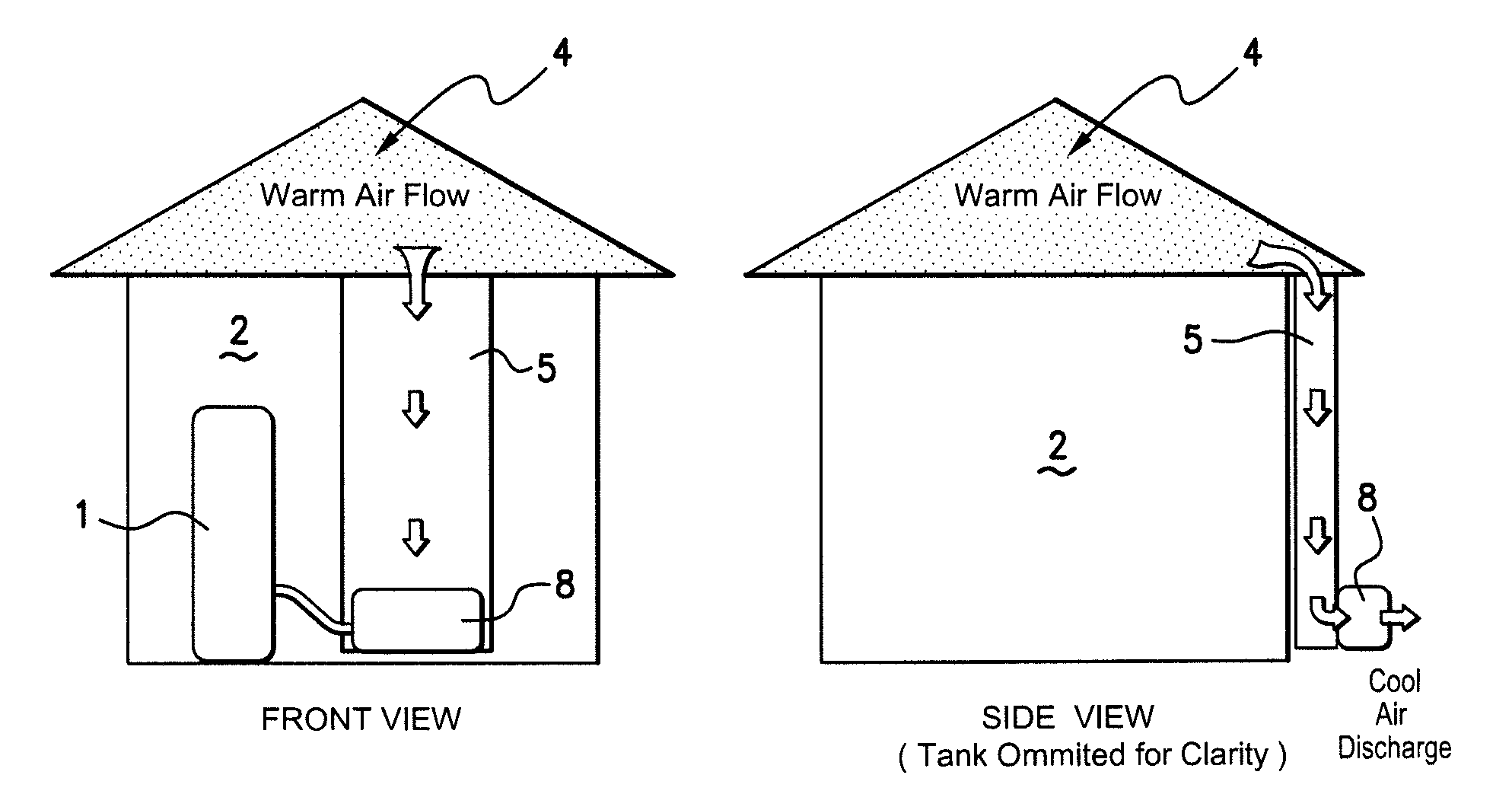
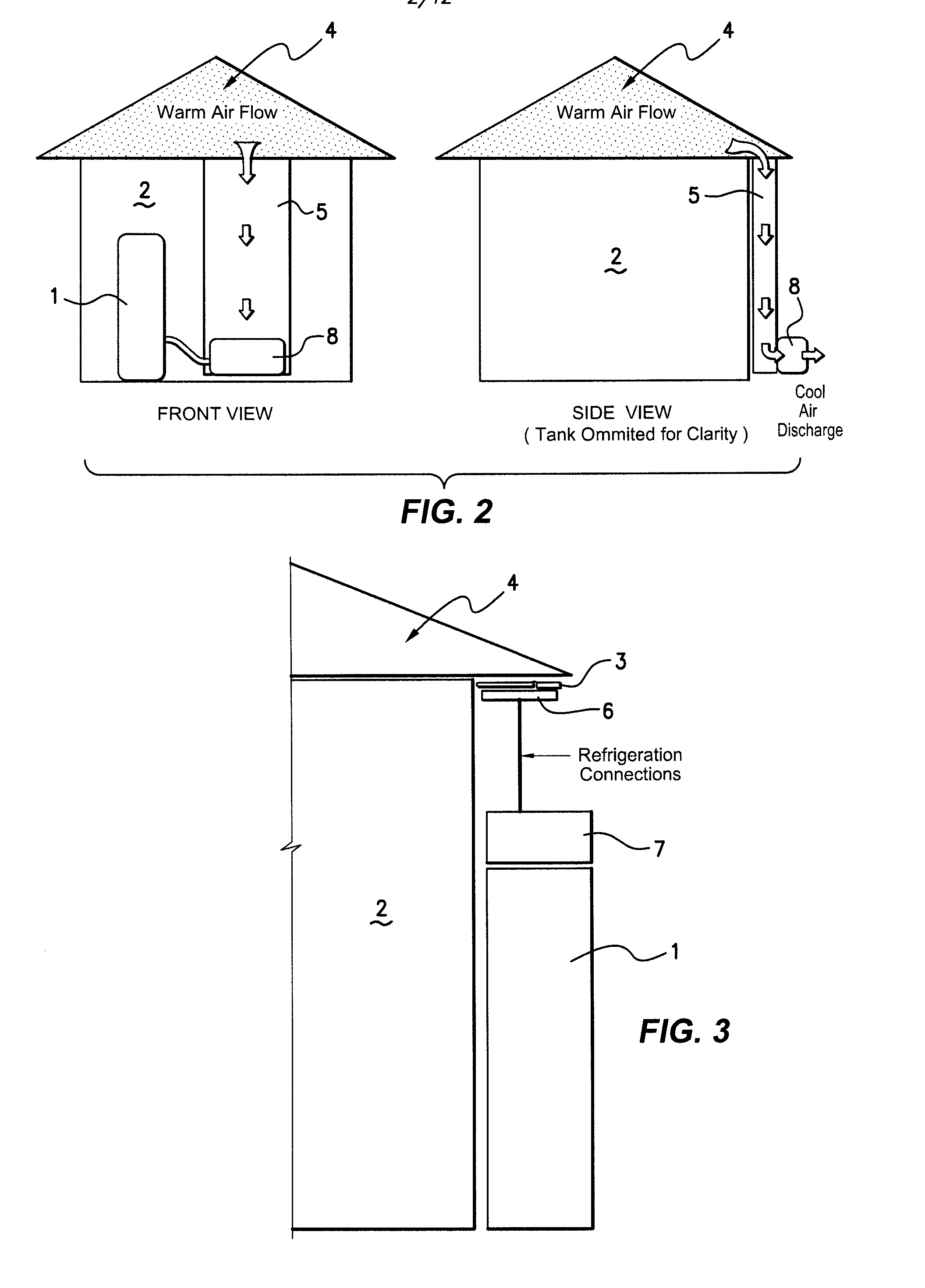
[0104]Referring now to FIG. 3, another embodiment of the invention, includes the physical separation of the heat pump 8 by separation of the compressor 7 and evaporator 3, thereby allowing ready positioning of the evaporator close to the preferred heat source, whilst involving minimal disruption to conventional building and installation procedures.

[0105]Whilst the previous examples exhibit substantial merit over prior art known, two disadvantages may occur in certain circumstances. For example, it can be difficult to install the heat pump embodiment as shown in FIG. 2, to a single story house without eaves or alternatively, to a multi-story building. In another example, such installations as shown in FIG. 2 may be regarded as aesthetically undesirable, due to the ducting required for retro-fitting to the side of the dwelling in question.

[0106]In order to address these issues, the invention as previously described has been modified with the provision of the heat pump into the roof sp...

example three

[0111]In another example of the invention the hardware of a conventional heat pump driven hot water system is used where the evaporator is mounted remotely from the tank inside the roof cavity of a home. In this example there is no ducting applied to the evaporator—which sits inside the roof cavity. The smart controller is programmed to operate the system when the roof cavity is warmest which dramatically improves the efficiency of the heat pump compared to a situation where the evaporator is outside on the ground.

[0112]Multiple (e.g. 2 or 3) temperature sensors are installed inside the water tank to allow the smart controller to monitor how much hot water has been used. These sensors will sense the amount of hot water remaining in the tank (high, low and very low). If hot water is used during the day and the amount of hot water drops below the “high” level then the smart controller will automatically start the heat pump and ensure the tank is completely full of hot water by the end...


PUM


Abstract

A heat pump system including a water reservoir tank, positioned proximate to a building, having a remote heat source associated therewith and ducting for drawing the heat source to the tank. The tank has an evaporator and a fan positioned to draw heat from the heat source and transfer the heat to the evaporator and a compressor for transferring the heat to the tank. A smart controller designed to optimize the efficiency of the heat pump water heaters may be used. The controller uses various inputs including ambient conditions and water consumption data to make an intelligent decision on when to run the system, based on a set of user preferences.

Description

CROSS-REFERENCE TO RELATED APPLICATIONS[0001]The present application claims priority from Australian Provisional Patent Application Nos 2010904258, 2011900535 and 2011901897 the contents of which are incorporated herein by reference.INTRODUCTION TO THE INVENTION[0002]The invention is the field of heat pumps, and in particular relates to a heat pump system adapted to efficiently utilise available heat sources.BACKGROUND TO THE INVENTION[0003]Heat pumps are most widely utilised for space heating and space cooling (often referred to as reverse cycle or split system air conditioners) or for heating water. Heat pumps are widely used in both domestic and industrial applications.[0004]Heat pumps are utilised reasonably successfully worldwide to heat air, cool air and heat water. There are however a number of key limitations associated with heat pumps. Despite being a relatively efficient source of heat exchange they still consume a significant amount of energy. For example, space heating, ...

Claims


Application Information

Patent Timeline
IPC IPC(8): F24D19/10F24D5/12F25B30/00
CPCF25B30/06Y02B30/52Y02B10/20Y02B10/70F24H4/04F24D17/001F24D17/02F24D19/1054F24D19/1063G05D23/1917F24D2200/14F24D2200/22F24D5/12F24D19/1087F25B30/00F25B2339/047Y02B30/18Y02B30/13Y02B30/12F24H15/281F24H15/38
Inventor ELLIOTT, STUARTSTEELE, BEN STEWARTSMITH, ROHAN
Owner PLANET INTPROP ENTERPRISES
Why Eureka
Eureka Blog
Learn More