Flexible Heat Sink With Lateral Compliance

Inactive Publication Date: 2013-08-22
I N T E R N A T I O N A L BUSINESS MACHINES
View PDF7 Cites 29 Cited by
  • Summary
  • Abstract
  • Description
  • Claims
  • Application Information

AI Technical Summary

Benefits of technology

[0022]The present invention provides structures, articles of manufacture and processes that address these needs to not only provide advantages over the related art, but also to substantially obviate one or more of the foregoing and other limitations and disadvant

Problems solved by technology

Flint et al., U.S. Pat. No. 4,964,458, show a heat exchanger for cooling an array of electric circuit chips disposed on a

Method used


Image

  • Flexible Heat Sink With Lateral Compliance
  • Flexible Heat Sink With Lateral Compliance
  • Flexible Heat Sink With Lateral Compliance

Examples


Embodiment Construction

[0034]To achieve the foregoing and other advantages, and in accordance with the purpose of this invention as embodied and broadly described herein, the following detailed description comprises disclosed examples of the invention that can be embodied in various forms.

[0035]The specific processes, compounds, compositions, and structural details set out herein not only comprise a basis for the claims and a basis for teaching one skilled in the art to employ the present invention in any novel and useful way, but also provide a description of how to make and use this invention. The written description, claims, abstract of the disclosure, and the drawings that follow set forth various features, objectives, and advantages of the invention and how they may be realized and obtained. These features, objectives, and advantages will also become apparent by practicing the invention.

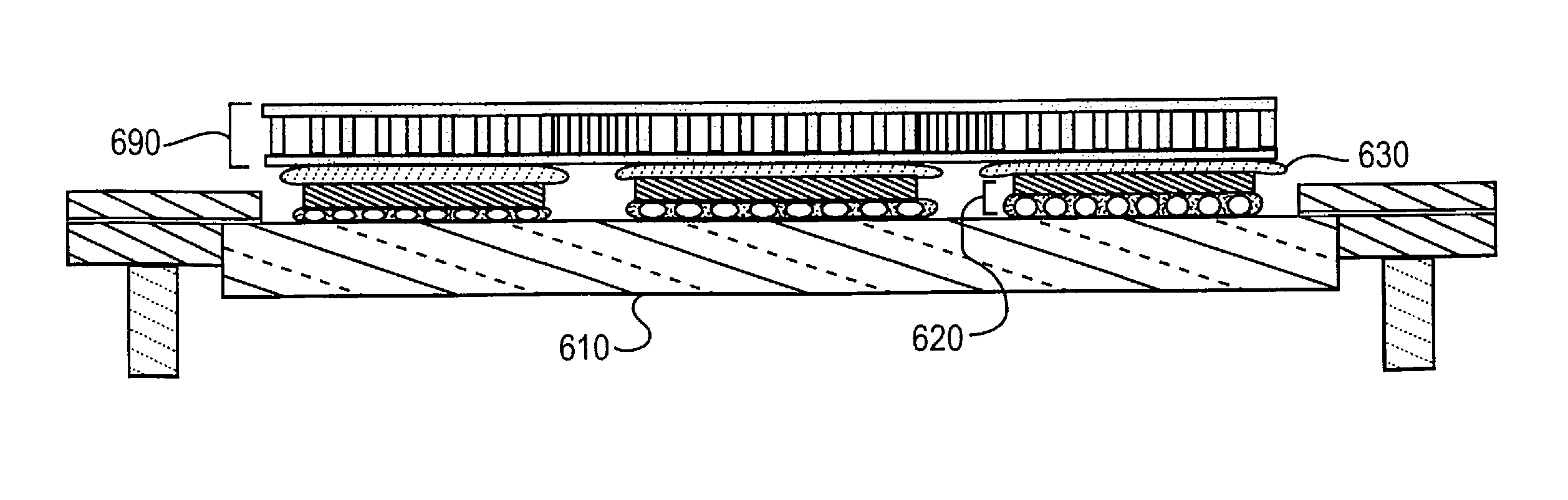
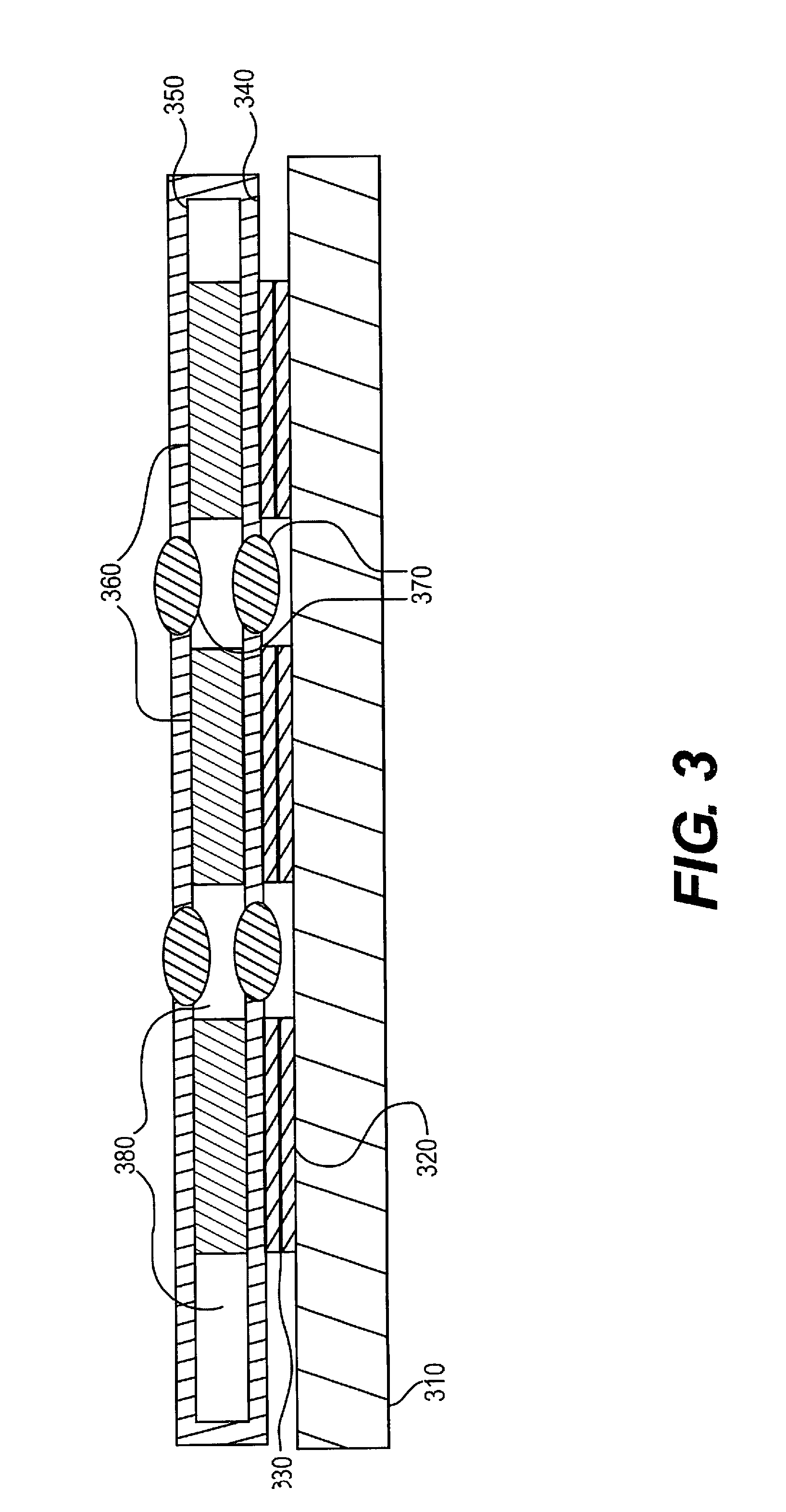
[0036]The invention comprises a flexible heat sink extending in a plane in an MCM where the heat sink comprises a t...


PUM


Abstract

A multi-chip module (MCM) structure comprises more than one semiconductor chip lying in a horizontal plane, the MCM having individual chip contact patches on the chips and a flexible heat sink having lateral compliance and extending in a plane in the MCM and secured in a heat exchange relation to the chips through the contact patches. The MCM has a mismatch between the coefficient of thermal expansion of the heat sink and the MCM and also has chip tilt and chip height mismatches. The flexible heat sink with lateral compliance minimizes or eliminates shear stress and shear strain developed in the horizontal direction at the interface between the heat sink and the chip contact patches by allowing for horizontal expansion and contraction of the heat sink relative to the MCM without moving the individual chip contact patches in a horizontal direction.

Description

FIELD OF THE INVENTION[0001]The filed of the invention in one aspect comprises a flexible heat sink with lateral complianceBACKGROUND OF THE INVENTION[0002]The so-called “silicon revolution” brought about the development of faster and larger computers beginning in the early 1960's with predictions of rapid growth because of the increasing numbers of transistors packed into integrated circuits with estimates they would double every two years. Since 1975, however, they doubled about every 18 months.[0003]An active period of innovation in the 1970's followed in the areas of circuit design, chip architecture, design aids, processes, tools, testing, manufacturing architecture, and manufacturing discipline. The combination of these disciplines brought about the VLSI era and the ability to mass-produce chips with 100,000 transistors per chip at the end of the 1980's, succeeding the large scale Integration (“LSI”) era of the 1970's with only 1,000 transistors per chip. (Carre, H. et al. “Se...

Claims


Application Information

Patent Timeline
IPC IPC(8): H01L23/36
CPCH01L23/46H01L25/0655H01L2224/16225H01L2224/32225H01L2224/73204H01L2224/73253H01L2924/00
Inventor SCHULTZ, MARK D.
Owner I N T E R N A T I O N A L BUSINESS MACHINES
Why Eureka
Try Eureka