
Apparatus and method for printing sharp image in an inkjet printer

a technology of inkjet printer and inkjet printing, applied in the direction of printing, other printing apparatus, etc., can solve the problems of inter-color bleeding, and affecting the quality of inkjet printing, so as to prevent coalescence and inter-color bleeding, and achieve cost advantage

Inactive Publication Date: 2013-08-22
MEIJET COATING & INKS
View PDF9 Cites 36 Cited by
  • Summary
  • Abstract
  • Description
  • Claims
  • Application Information

AI Technical Summary

Benefits of technology

The patent text describes an invention of an apparatus and method for printing with aqueous ink on uncoated and untreated media. The apparatus includes a heating mechanism to speed up the drying process and prevent color bleeding and a cooling mechanism to maintain the printhead temperature below a certain limit. The technical effect is to provide a cost-effective solution for printing with environmentally-friendly ink on untreated media.

Problems solved by technology

The prolonged ink fluid ability and the ability for ink component to dissipate can cause image quality to degrade substantially, especially in an area where ink load is high.
The edges of color patches can become soft, ragged and feathering.
When two patches of different colors share a boundary, slower than adequate dry time may cause inter-color bleeding, an undesirable image quality artifact.
When ink droplets are ejected from the printhead and land on media, the volatile solvents quickly evaporates and ink on the media dries rapidly.
However, fume from the evaporated solvents usually has strong odor and is harmful to operators running the printers and pollutes to the environment.
Since solvents of any type are not good for our health and unfriendly to environment, the genuinely healthy and environment-friendly ink has its ink vehicle based on water instead of solvents.
As such manufacturing of the rapid dry type of media is costly and energy intensive.
However, such a drying system does not support aqueous ink printing on uncoated media because the ink drying system is located downstream of the print zone.
The time internal between printing and media dying causes perceivable image quality degradation due to coalescence and ink bleeding when uncoated media is used.
However, in such a system heat transferred to the media inadvertently heats up the nozzles on the printhead that travels in the print zone for printing.
The consequence is dried and clogged the nozzles.
If aqueous ink is used for printing, more extensive nozzle maintenance is necessary, or image quality suffers.
In practice, this type if printing system caused issues with printhead reliability and image quality.
Ink heating prior to jetting and especially the heat dissipated from the pre-heated media to the nozzles on the printhead caused ink in the nozzles to dry and hence clogged nozzles.

Method used


Image

  • Apparatus and method for printing sharp image in an inkjet printer
  • Apparatus and method for printing sharp image in an inkjet printer
  • Apparatus and method for printing sharp image in an inkjet printer

Examples


Embodiment Construction

[0023]The present description will be directed in particular to elements forming part of, or cooperating more directly with, apparatus and methods in accordance with the present invention. It is to be understood that elements not specifically shown or described may take various forms well known to those skilled in the art.

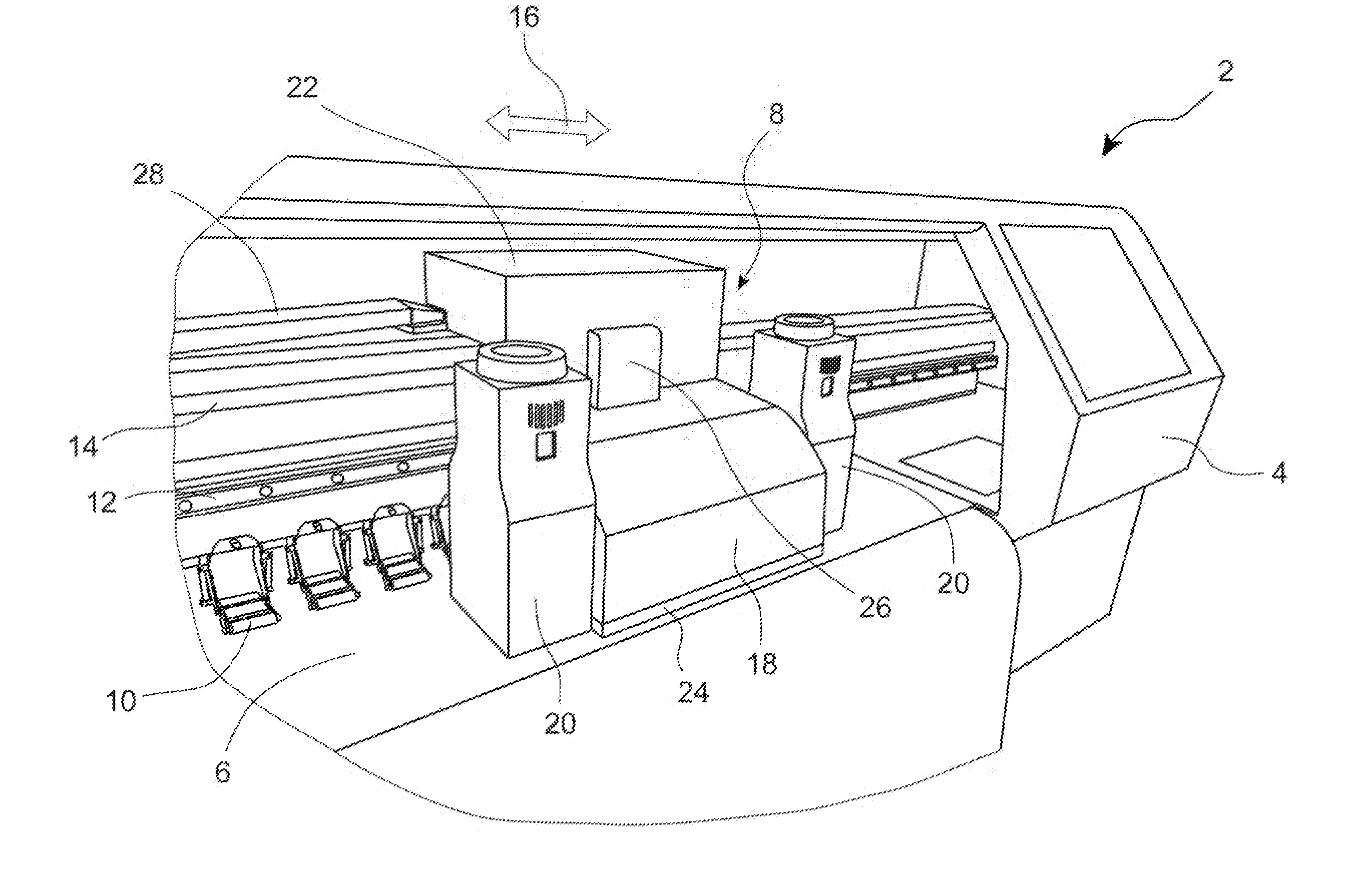
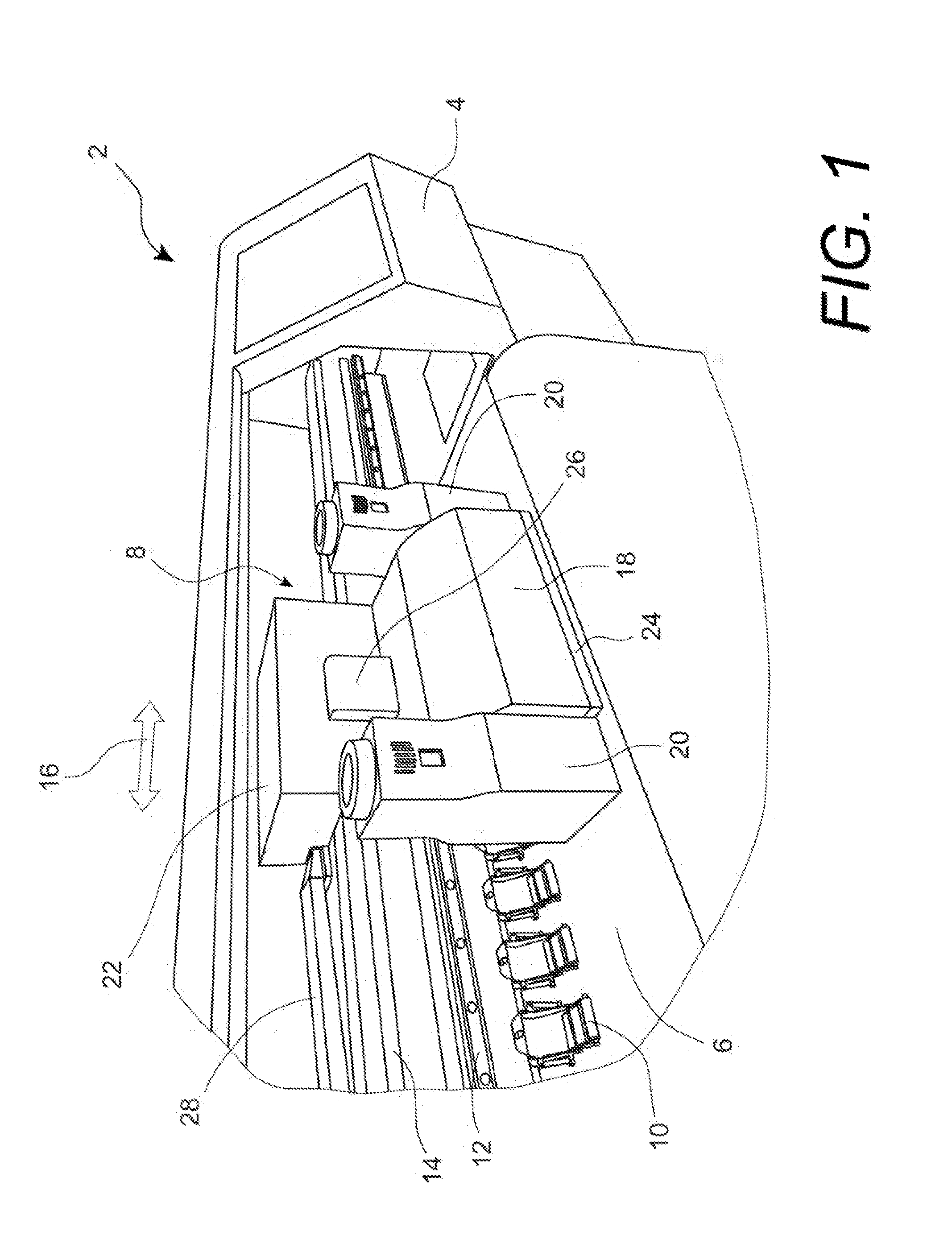
[0024]Referring to FIG. 1, an example of a wide format inkjet printer 2 is partially shown with the front cover removed to reveal the modules and components that are critical for printing an image. A wide format or large format inkjet printer is typically floor standing, and is capable of printing on media larger than A2 or wider than 17″. In contrast, a desk-top or an office printer typically prints on media sized up to 8.5″ by 11″ or 11″ by 17″, or the metric standard A4 or A3. Printer 2 has right side housing 4 and a left side housing (not shown) to enclose various electrical and mechanical components, including a main PC board (not shown) and ink supplies of di...


PUM


Abstract

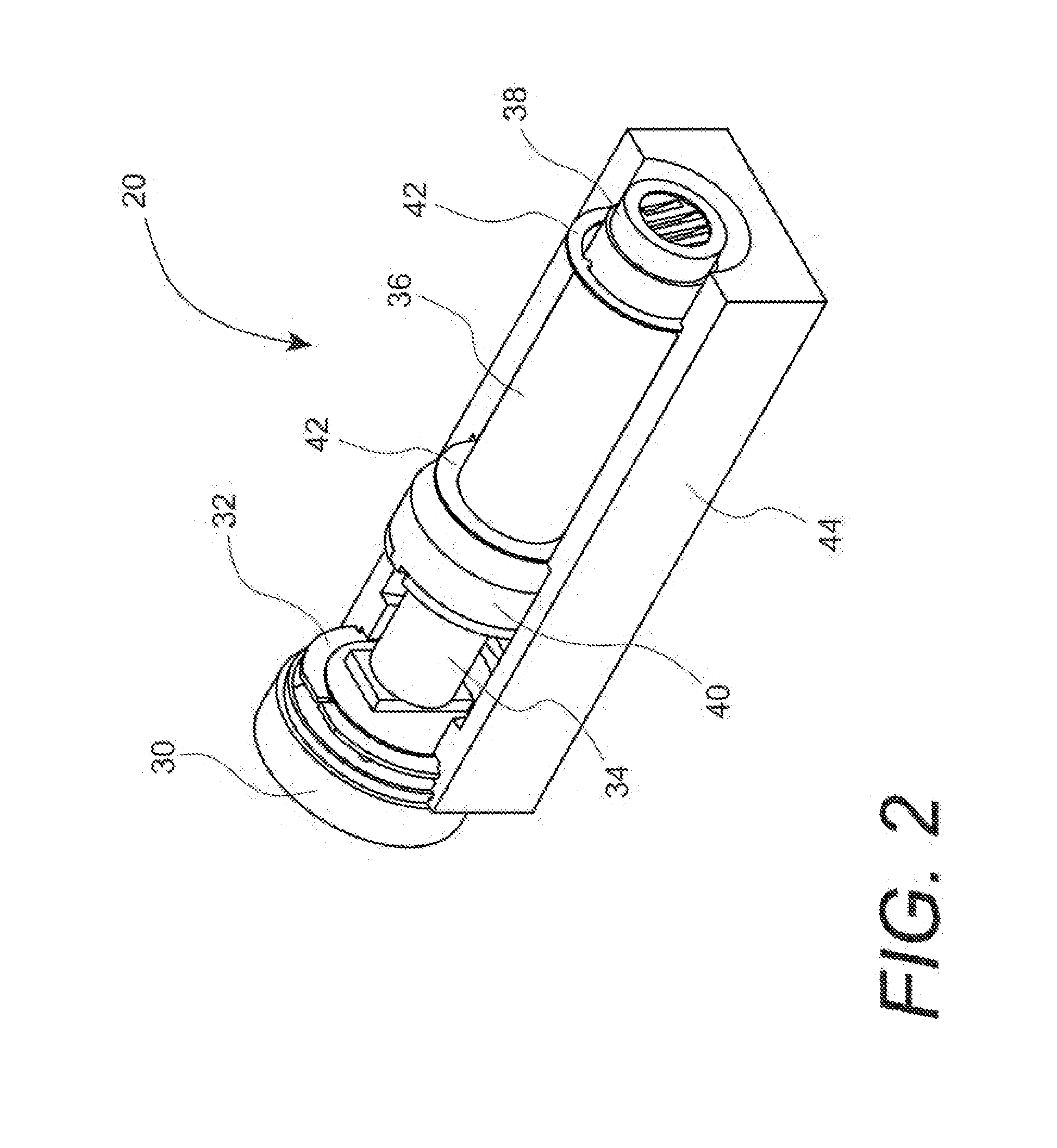
An apparatus and method to heat media in order to achieve rapid ink drying for sharp image quality is disclosed. The apparatus comprises a media heating means to heat media approximate the print zone to prevent coalescence and inter-color bleeding, and a printhead cooling means to cool the printhead so that the printhead temperature is maintained below an upper printhead temperature limit to minimize clogged nozzles. The preferred embodiment includes a hot air blower attached to the movable carriage to impinge heated air directly on to the media surface, and circulating a liquid coolant in a fluid channel built in a printhead plate conductively connected to the printhead.

Description

FIELD OF THE INVENTION[0001]The present invention relates generally to inkjet printing, and more particularly to printing sharp images in an inkjet printer by heating the media and drying the ink thereon and cooling the printhead.BACKGROUND OF THE INVENTION[0002]An inkjet printer typically includes a carriage holding a printhead thereon, a platen, and a print engine that has electronics including microchips to send out instructions for printing. The platen is coupled with a driving mechanism to transport media, i.e., the printing substrate, in a media movement direction. The printhead has small nozzles thereon that can eject out tiny ink droplets following instructions received from the print engine. The carriage is capable of traveling back and forth along a carriage scanning direction, which is typically perpendicular to the media movement direction. The combination of media movement and carriage movement ensures that ink droplets ejected from the printhead can land anywhere in a ...

Claims


Application Information

Patent Timeline
Patent Type & Authority Applications(United States)
IPC IPC(8): B41J2/01
CPCB41J11/002B41J29/377B41J11/02B41J11/0021B41J11/00216B41J11/0022B41J11/0024
Inventor CHEN, WEN
Owner MEIJET COATING & INKS
Learn More