Display apparatus and method for adjusting three-dimensional effects

a display apparatus and three-dimensional effect technology, applied in the field of display apparatus and a three-dimensional effect adjustment method of the display apparatus, can solve the problems of difficult control of the disparities of all objects, and the 3d effect actually intended by a producer is not properly expressed

Inactive Publication Date: 2013-08-22
SAMSUNG ELECTRONICS CO LTD
View PDF2 Cites 4 Cited by
  • Summary
  • Abstract
  • Description
  • Claims
  • Application Information

AI Technical Summary

Benefits of technology

[0008]One or more exemplary embodiments may provide a display apparatus capable of ascertaining whether a 3D effect intended by a producer is expressed, adjusting the 3D effect, and a method of adjusting the 3D effect.
[0016]According to another aspect of an exemplary embodiment, there is provided a method of adjusting a three-dimensional (3D) effect of a display apparatus, the method including: receiving a 3D video signal including a left-eye video signal and a right-eye video signal; calculating disparity information showing the difference in a visual point between the left-eye video signal and the right-eye video signal; calculating first depth information of the 3D video signal based on the calculated disparity information and photographing information from a 3D image photographing device that generates the 3D video signal; generating and displaying a first depth map based on the first depth information; generating and displaying a menu button for adjusting the first depth information; and generating and displaying a second depth map based on second depth information, in response to a user's selection input through the menu button.

Problems solved by technology

When an image is taken through a camera, it is difficult to control the disparities of all objects due to problems relating to image distortion, and the like.
Therefore the problem exists that a 3D effect actually intended by a producer is not properly expressed.

Method used


Image

  • Display apparatus and method for adjusting three-dimensional effects
  • Display apparatus and method for adjusting three-dimensional effects
  • Display apparatus and method for adjusting three-dimensional effects

Examples


Embodiment Construction

[0028]Below, exemplary embodiments will be described in detail with reference to the accompanying drawings so as to be easily understood by a person having ordinary skill in the art. The exemplary embodiments may be embodied in various forms without being limited to the exemplary embodiments set forth herein. Descriptions of well-known parts are omitted for clarity, and like reference numerals refer to like elements throughout.

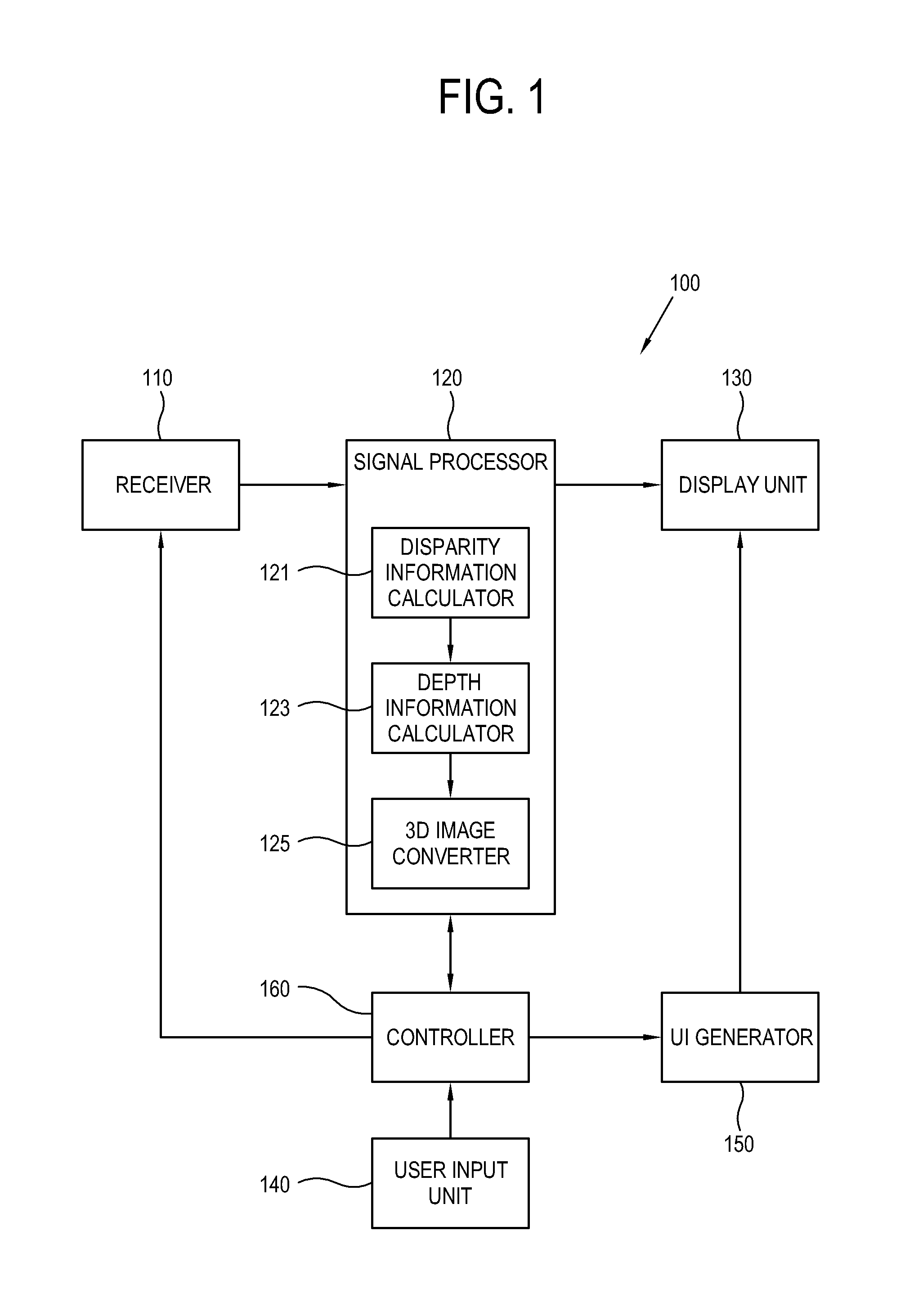
[0029]FIG. 1 is a control block diagram of a display apparatus according to an exemplary embodiment.

[0030]Referring to FIG. 1, a display apparatus 100 includes a receiver 110, a signal processor 120, a display unit 130, a user input unit 140, a user interface (UI) generator 150, and a controller 160 which controls the other elements of FIG. 1.

[0031]The display apparatus 100 may calculate disparity information of a stereoscopic video signal (or a 3D video signal) received from a 3D image photographing device (not shown), and may calculate depth information base...


PUM


Abstract

A display apparatus and a method for adjusting a 3D effect of the display apparatus are disclosed. The display apparatus includes: a display unit; a receiver which receives a three-dimensional (3D) video signal including a left-eye video signal and a right-eye video signal; a disparity information calculator which calculates disparity information; a depth information calculator which calculates first depth information of the 3D video signal and photographing information of a 3D image photographing device; a 3D image converter which generates a first depth map and displays the first depth map; and a user interface (UI) generator which generates and displays a menu button for adjusting the first depth information, the 3D image converter generating a second depth map in response to a user's selection input through the menu button, and displaying the second depth. With the intention of a 3D image producer to adjust the 3D effect.

Description

CROSS-REFERENCE TO RELATED APPLICATION[0001]This application claims priority from Korean Patent Application No. 10-2012-0016162, filed on Feb. 17, 2012 in the Korean Intellectual Property Office; the disclosure of which is incorporated herein by reference.BACKGROUND[0002]1. Field[0003]Apparatuses and methods consistent with the exemplary embodiments relate to a display apparatus and a method for adjusting a three-dimensional (3D) effect of the display apparatus. More particularly, the exemplary embodiments relate to a display apparatus capable of adjusting a 3D effect of a 3D image in accordance with production intention, and a method of adjusting the 3D effect.[0004]2. Description of the Related Art[0005]A stereoscopic image (or a 3D image) is photographed using two or more cameras or a stereo camera. Such a photographed 3D image gets a horizontal disparity which corresponds to positions and depth of an object. The horizontal disparity becomes a factor in determining a level of a 3...

Claims


Application Information

Patent Timeline
Patent Type & Authority Applications(United States)
IPC IPC(8): H04N13/00
CPCH04N2013/0081H04N13/0029H04N13/0022H04N13/128H04N13/139
Inventor YUN, SANG-UNKIM, HYUNG-RAEPARK, JAE-SUNGSUNG, JUN-HOCHO, BONG-HWANHWANG, MIN-CHEOL
Owner SAMSUNG ELECTRONICS CO LTD
Why Eureka
Try Eureka