Fault clearing without a DC backup power source

a technology of backup power source and fault clearing, applied in the field of electric power systems, can solve problems such as failur

Active Publication Date: 2013-08-22
SIKORSKY AIRCRAFT CORP
View PDF2 Cites 15 Cited by
  • Summary
  • Abstract
  • Description
  • Claims
  • Application Information

AI Technical Summary

Problems solved by technology

In some cases, the remaining load busses can overload the remaining generator, resulting in its failure as well.

Method used


Image

  • Fault clearing without a DC backup power source
  • Fault clearing without a DC backup power source
  • Fault clearing without a DC backup power source

Examples


Embodiment Construction

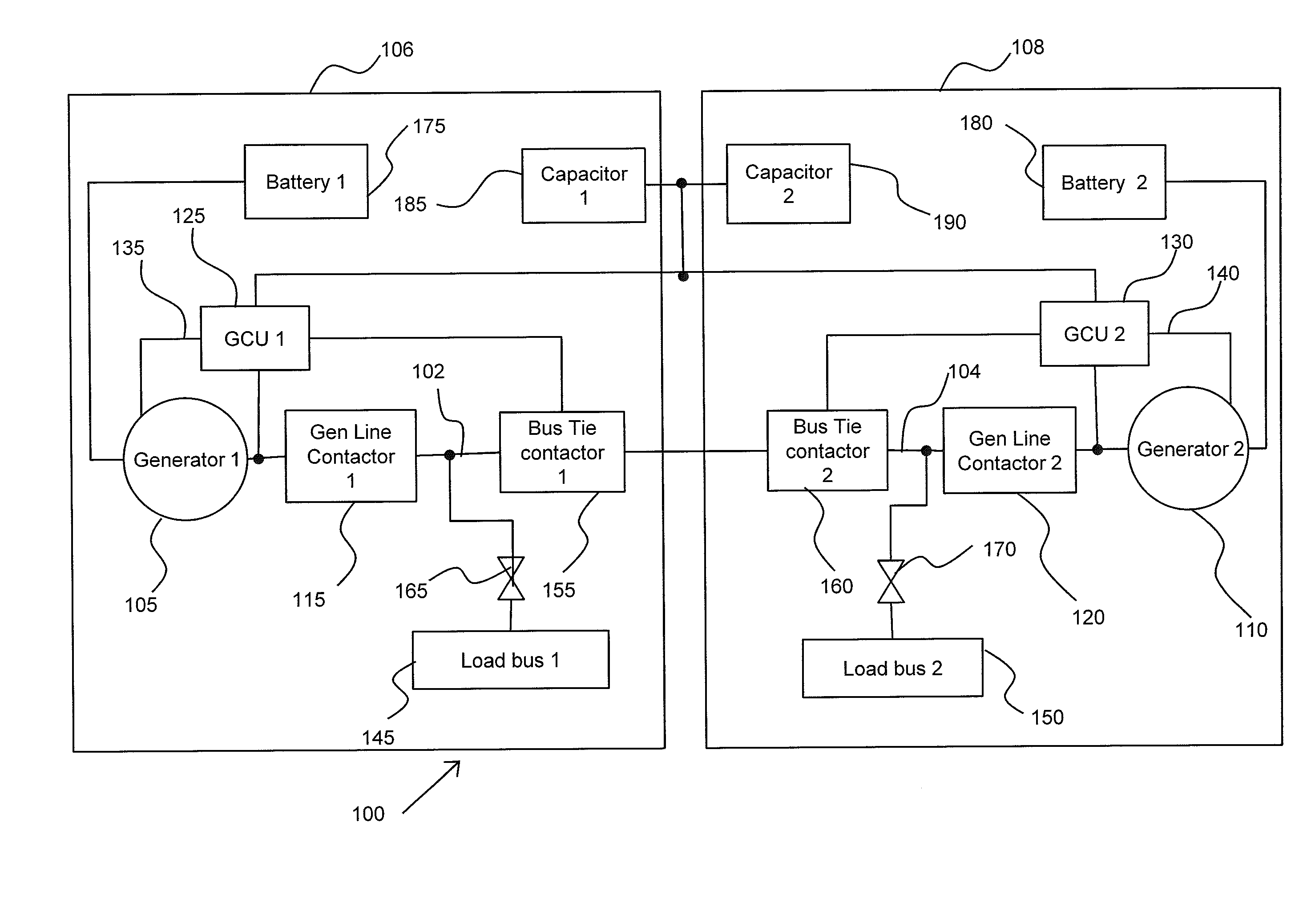
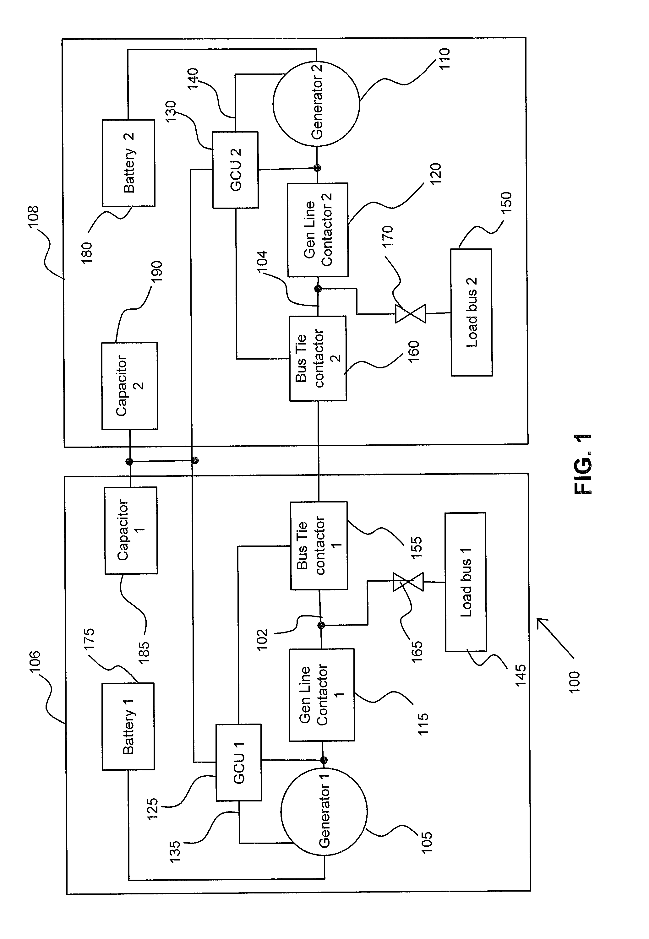
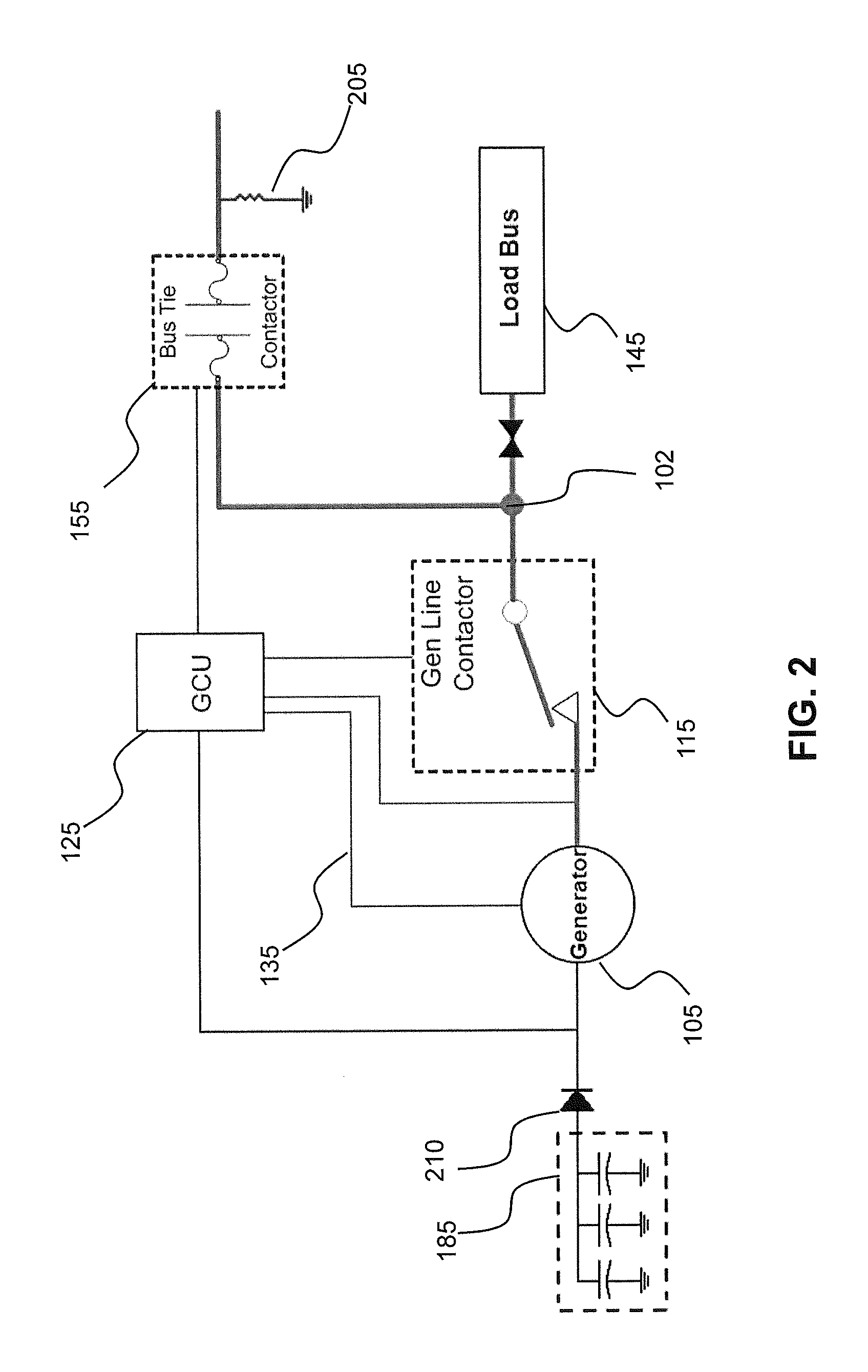
[0009]Embodiments of an aircraft's electrical power protection system includes a DC electrical power system having a capacitor bank for selectively applying power to the system when back up battery power is not available to clear a ground fault. The system includes a capacitor bank connected to a field line of a self-excited generator for supplying hold-up power to the generator during a fault clearing mode. Additionally, the capacitor bank supplies power to the logic circuits of a bus tie contactor for maintaining its logic during the fault clearing mode as well as for selectively opening the logic circuit and isolating the fault from the main circuit.

[0010]Referring now to the drawings, FIG. 1 illustrates a schematic block diagram of an aircraft's electrical power protection system 100 having a plurality of engines 106, 108 including generators 105, 110 for selectively applying power to the power protection system 100 in order to clear a ground fault according to an embodiment of ...


PUM


Abstract

An electrical power protection system, includes a generator configured for supplying Direct Current (DC) power to a load bus, the load bus in electrical communication with a bus circuit; a generator control unit being configured for regulating the output voltage supplied by the generator; a bus contactor in serial communication with the bus circuit, the bus contactor including logic circuits configured for detecting an overcurrent in the bus circuit, the overcurrent representative of a ground fault in the bus circuit; and a capacitor bank coupled to the generator for selectively supplying an excitation voltage through a diode switch to the generator during the ground fault in the bus circuit.

Description

FIELD OF INVENTION[0001]The subject matter disclosed herein relates generally to the field of electrical power systems and, particularly, to an aircraft's electrical power system having a capacitor source for supplying power to a self-excited generator in order to maintain the generators field during a fault clearing mode.DESCRIPTION OF RELATED ART[0002]Typically, an aircraft's electrical power system includes a DC power generator as a primary power source with batteries serving as an emergency backup power source. The DC power generator is used to start an aircraft's engine and, once started, the engines cause power generation through the power generators resulting in electrical power being supplied to load busses in the electrical power system. A typical twin engine generator power system would consist of two generators, one per engine. A first generator would be used for starting the first engine and for providing, for example, electrical power to the left hand busses. A second g...

Claims


Application Information

Patent Timeline
Patent Type & Authority Applications(United States)
IPC IPC(8): H02H9/02
CPCH02H7/268
Inventor EISENHAUER, MARK P.SULLIVAN, CHRISTOPHER PATRICK
Owner SIKORSKY AIRCRAFT CORP
Why Eureka
Try Eureka