In-sequence delivery of upstream user traffic during handover

a technology of user traffic and in-sequence delivery, applied in the direction of multiplex communication, wireless communication, frequency-division multiplex, etc., can solve the problems of severe impact on data transport, and achieve the effect of improving upstream user traffic forwarding

Active Publication Date: 2013-08-22
ALCATEL LUCENT SAS
View PDF9 Cites 23 Cited by
  • Summary
  • Abstract
  • Description
  • Claims
  • Application Information

AI Technical Summary

Benefits of technology

[0029]It is an object of the present invention to improve upstream user traf

Problems solved by technology

This results in upstream data packets arriving at the S-GW out of sequence, which in turn

Method used


Image

  • In-sequence delivery of upstream user traffic during handover
  • In-sequence delivery of upstream user traffic during handover
  • In-sequence delivery of upstream user traffic during handover

Examples


Embodiment Construction

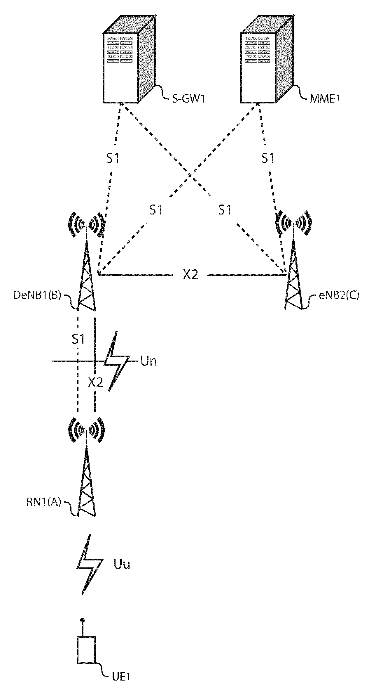
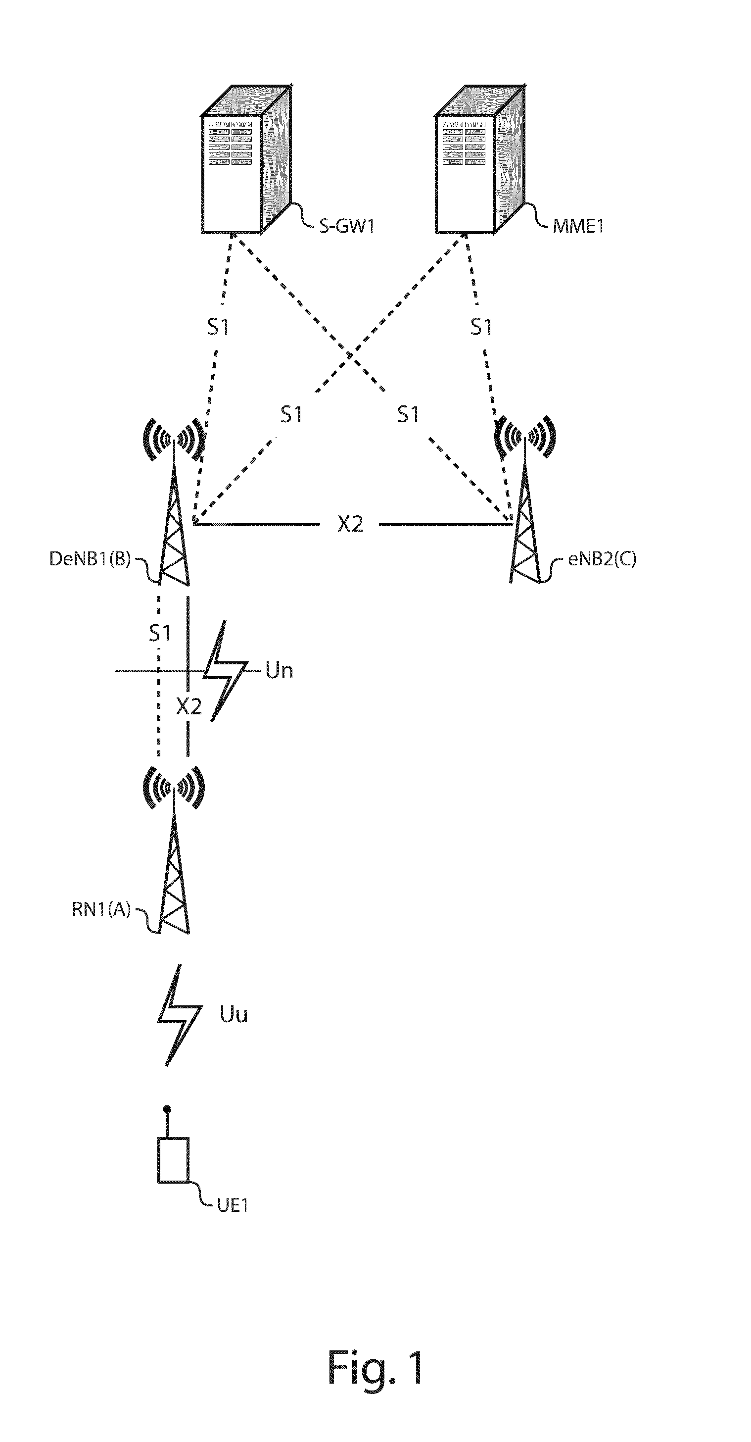
[0060]There is seen in FIG. 1 part of an LTE Public Land Mobile Network (PLMN) comprising the following network nodes:

[0061]an MME MME1,

[0062]a S-GW S-GW1,

[0063]3 eNBs RN1, DeNB1 and eNB2,

[0064]a UE UE1, such as a mobile terminal.

[0065]The eNBs DeNB1 and eNB2 are directly coupled to the MME MME1 and to the S-GW S-GW1 through an S1 interface. The eNB DeNB1 is a DeNB that wirelessly connects (via Un interface) the RN RN1 to the Evolved Packet Core (EPC). The DeNB DeNB1 acts as an S1 proxy for S1 connections between the RN RN1 and the MME MME1 and the S-GW S-GW1, and as an X2 proxy for X2 connections between the RN RN1 and further eNBs.

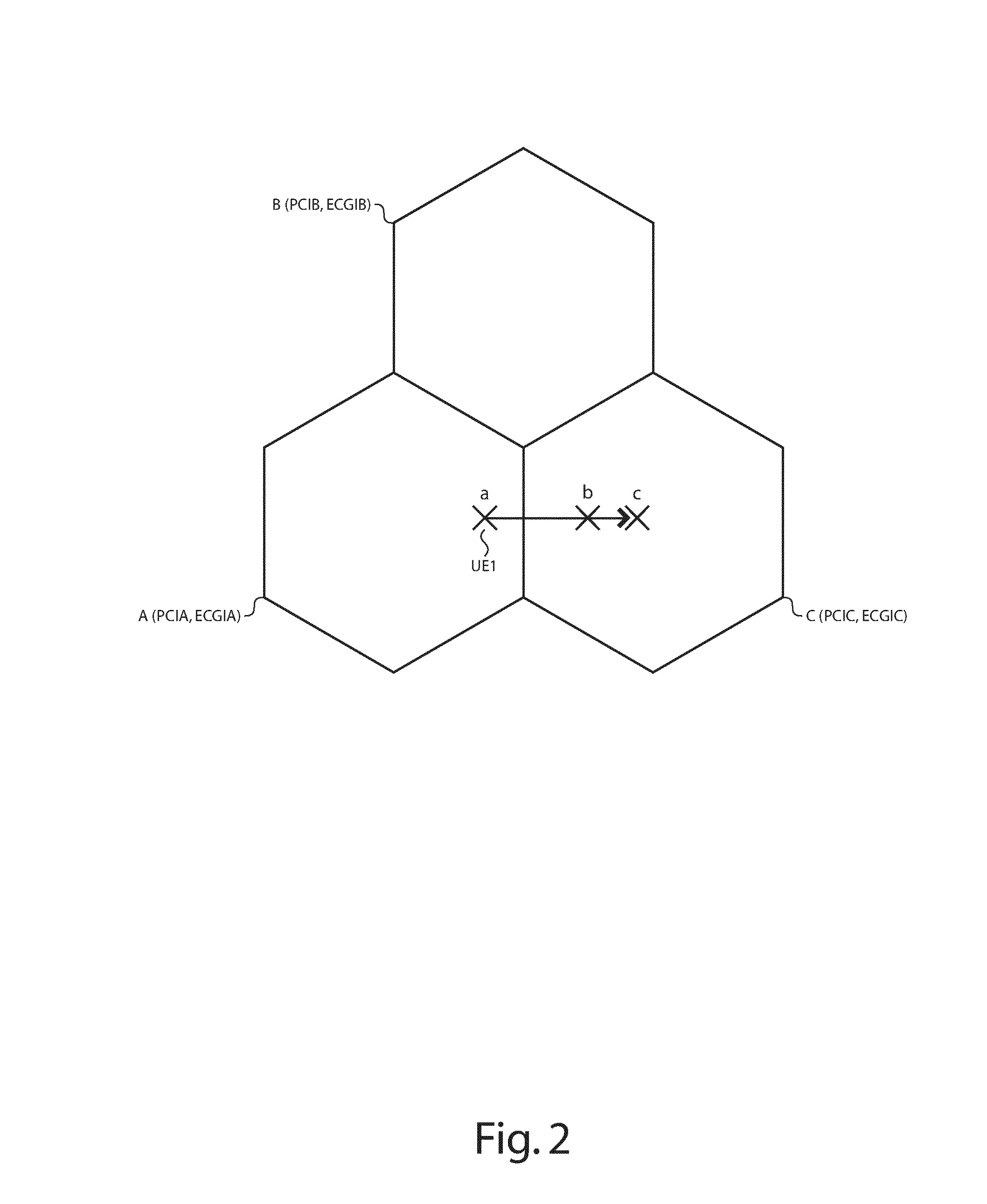
[0066]There is seen in FIG. 2 a radio coverage area comprising 3 cells A, B and C respectively operated by the eNBs RN1, DeNB1 and eNB2.

[0067]The 3 cells A, B and C are assumed to belong to the same Tracking Area (TA), and have PCIA, PCIB and PCIC as Physical Cell Identifiers (PCI), and further have ECGIA, ECGIB and ECGIC as Evolved Cell Global Identifie...


PUM


Abstract

The present invention relates to a donor radio access node (DeNB1) configured to wirelessly connect to, and to proxy operation of a source relay node (RN1), and further configured to forward upstream user traffic towards a serving gateway (S-GW1) during a handover of a particular mobile device (UE1) from a source cell (A) operated by the source relay node to a target cell (C) operated by a target radio access node (eNB2). In accordance with an embodiment of the invention, the donor radio access node comprises: —first forwarding means (FW1) for forwarding a sequence of upstream data packets (P1, P2, P3) from the source relay node to the serving gateway, which sequence of upstream data packets comprising upstream data packets up to a particular packet sequence number (Y−1), —second forwarding means (FW2) for forwarding a data transfer status message (SN STATUS TRANSFER) for the particular mobile device from the source relay node to the target radio access node, which data transfer status message comprising an information element (Y) indicative of the particular packet sequence number, wherein the donor radio access node comprises a forwarding controller (CTRL) coupled to the first and second forwarding means, and configured to interdependently control forwarding of the data transfer status message and of any pending upstream data packet (P2, P3) out of the sequence of upstream data packets that has not been yet validly forwarded to the serving gateway. The present invention also relates to a method for forwarding upstream user traffic towards a serving gateway during a handover.

Description

TECHNICAL FIELD OF THE INVENTION[0001]The present invention relates to in-sequence delivery of upstream user traffic during a handover procedure.TECHNICAL BACKGROUND OF THE INVENTION[0002]Handover is the process of transferring an ongoing communication session, being a voice / video call or a data session, from the current serving cell, further referred to as the source cell, towards a new better-suited cell, further referred to as the target cell. For instance, as a User Equipment (UE) is moving away from the coverage area of a serving cell, the radio signal from that serving cell weakens while the radio signal from another better-suited cell strengthens. When the radio path loss between these two cells is past a predetermined threshold, a handover towards the better-suited cell is triggered. A UE may also be handed over on account of Radio Resource Management (RRM) criterion, for instance because the serving cell gets overloaded.[0003]For Long Term Evolution (LTE) mobile networks, a...

Claims


Application Information

Patent Timeline
IPC IPC(8): H04W36/02
CPCH04W36/02H04L47/34
Inventor WORRALL, CHANDRIKAPALAT, SUDEEP
Owner ALCATEL LUCENT SAS
Why Eureka
Try Eureka