Rotary lobe pump with wiper blades

a rotary lobe, wiper blade technology, applied in the direction of rotary/oscillating piston pump components, machines/engines, liquid fuel engines, etc., can solve the problems of high manufacturing cost, many rotary pumps are difficult and expensive to maintain, and the efficiency of rotary pumps is improved. , the effect of reducing the manufacturing cost of making such a pump

Inactive Publication Date: 2013-08-22
PMC LIQUIFLO EQUIP
View PDF6 Cites 12 Cited by
  • Summary
  • Abstract
  • Description
  • Claims
  • Application Information

AI Technical Summary

Benefits of technology

[0007]Therefore, it is an object of the present invention to improve the efficiency of a rotary pump and to reduce the manufacturing costs of making such a pump. It is a further object of the present invention to provide an improved impeller which has removable, extended-wear wiper blades which can be replaced quickly and cost effectively. Another object is to assure contact between the wiper blades and either the housing or other imp

Problems solved by technology

As such, rotary pumps are expensive to manufacture and may suffer from a lack of a high degree of tolerance.
Furthermore, many rotary pumps are difficult and expensive to maintain since after excessive wear, the entire impeller(s) require replacement.
However, packing materials wear out quickly which reduces efficiency of the pump unless the packing material is replaced frequently.
Additionally, materials such as felt are semi-porous which allows flow though the material and reduces efficiency.
Furthermore, the packing mater

Method used


Image

  • Rotary lobe pump with wiper blades
  • Rotary lobe pump with wiper blades
  • Rotary lobe pump with wiper blades

Examples


Embodiment Construction

[0028]The present invention generally relates to an improved semi-positive displacement rotary pump. More particularly, the present invention provides an improved impeller for use in a rotary pump.

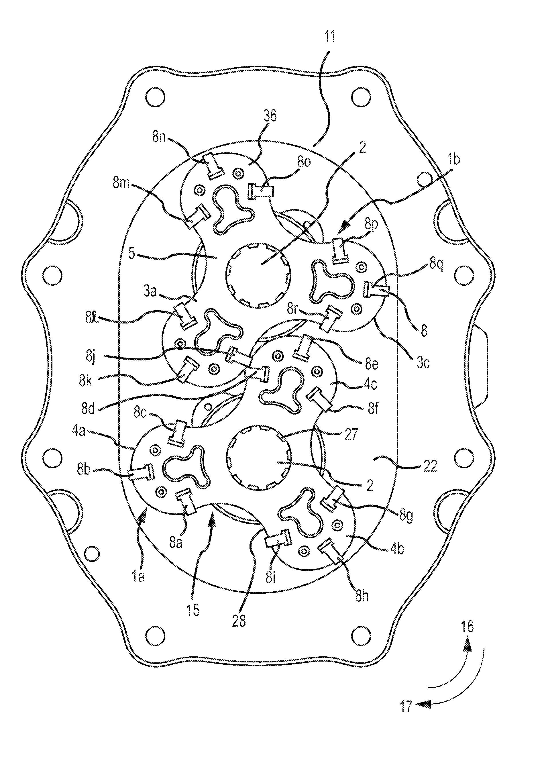
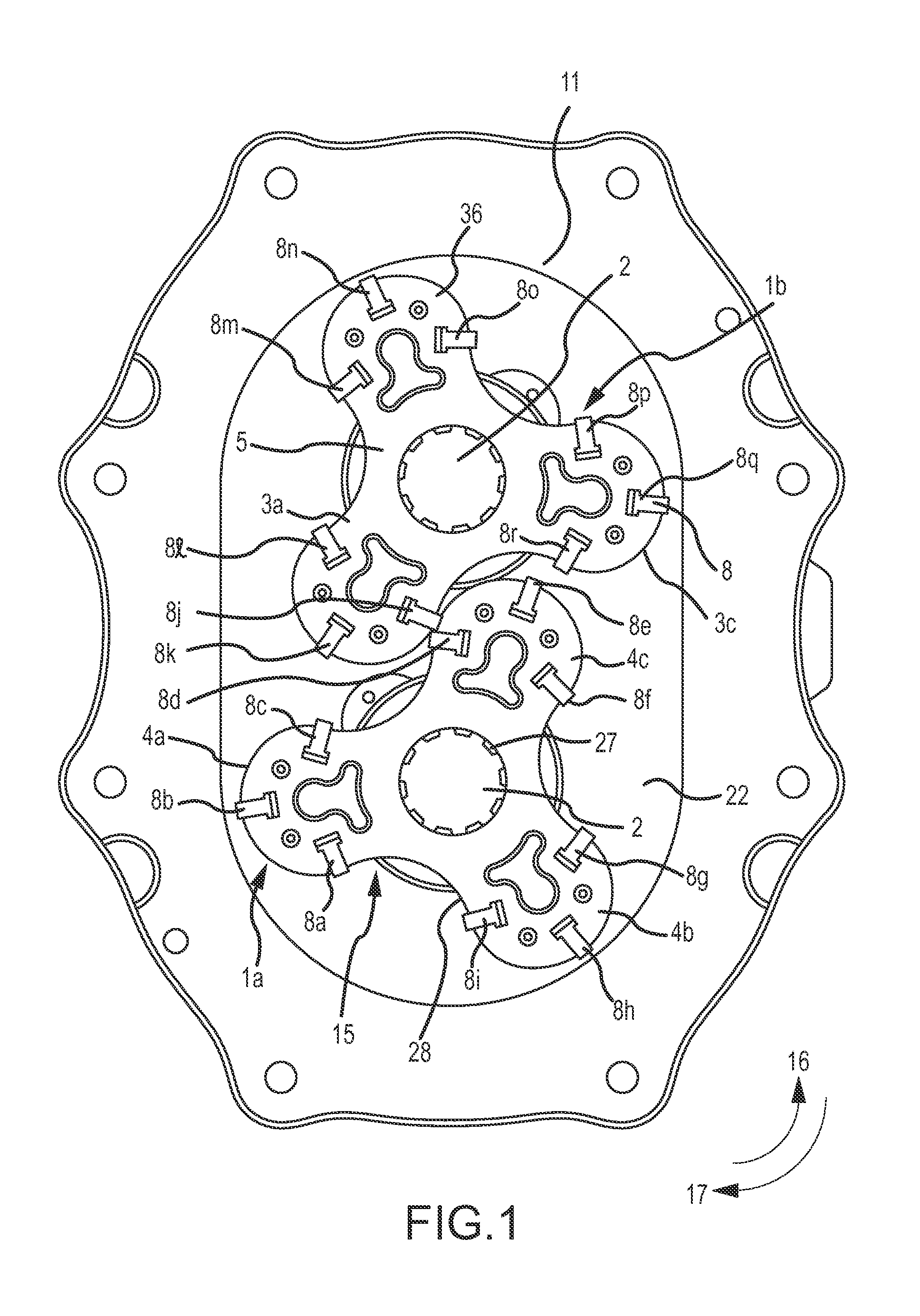
[0029]Referring now to FIG. 1, impellers 1a, 1b are provided with a plurality of wiper inserts 8 which are secured about a periphery of one or more impeller lobes 3. In one embodiment, the wiper inserts 8 are operatively positioned near or within a cavity 10 of the impeller lobe 3 such that the wiper insert 8 is in direct contact with an interior chamber wall 11 of a pump chamber 22 or a substantially arcuate cut-out portion of the other impeller. Thus, the efficiency of the pump is improved compared to conventional rotary pumps which require a gap between the end of the impeller lobe peripheries 4 and the chamber wall 11 or other impeller to prevent excessive vibration.

[0030]One advantage of the improved impeller for a rotary pump of the present invention is that the close tolerances of t...


PUM


Abstract

A positive displacement rotary pump with an improved impeller design integrating replaceable wiper inserts. The impeller generally has or more lobes and an equal number of conjugate surfaces. Each lobe has an arcuate peripheral end comprising a plurality of wiper blades. The wiper blades improve efficiency by making a seal with a pump chamber or the conjugate surface on the other impeller as it rotates. The wiper blades are arranged such that constant and successive contact between wiper blades and impellers is achieved.

Description

RELATED APPLICATIONS[0001]This Non-Provisional Patent Application claims the benefit of priority from U.S. Provisional Patent Application No. 61 / 597,569, filed Feb. 10, 2012, the entire disclosure of which is hereby incorporated by reference in its entirety.FIELD OF THE INVENTION[0002]The present invention relates to an improved semi-positive displacement rotary pump. More particularly, the pump has an improved impeller with a replaceable wiper inserts in the impeller lobes to improve the efficiency and performance.BACKGROUND[0003]The prior art includes many rotary pumps for pumping liquids such as water, oil, gasoline, and other materials. In such pumps, the tolerance of clearance between the impellers and the pump chamber is critical to the proper functioning of the pump. The clearance must be great enough so the impellers do not touch a pump chamber wall and destroy various components of the pump, yet small enough that the pump operates efficiently and with minimal vibration by p...

Claims


Application Information

Patent Timeline
IPC IPC(8): F04C15/00
CPCF04C2/084F04C15/0015F04C2/126
Inventor DIXON, RANDYHOWELL, BRETT
Owner PMC LIQUIFLO EQUIP
Why Eureka
Try Eureka