

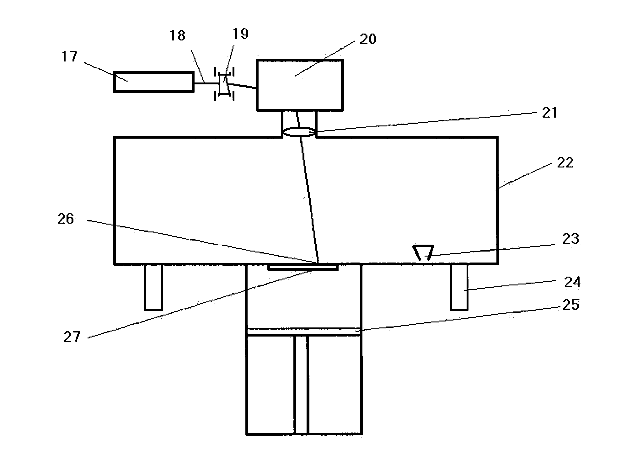
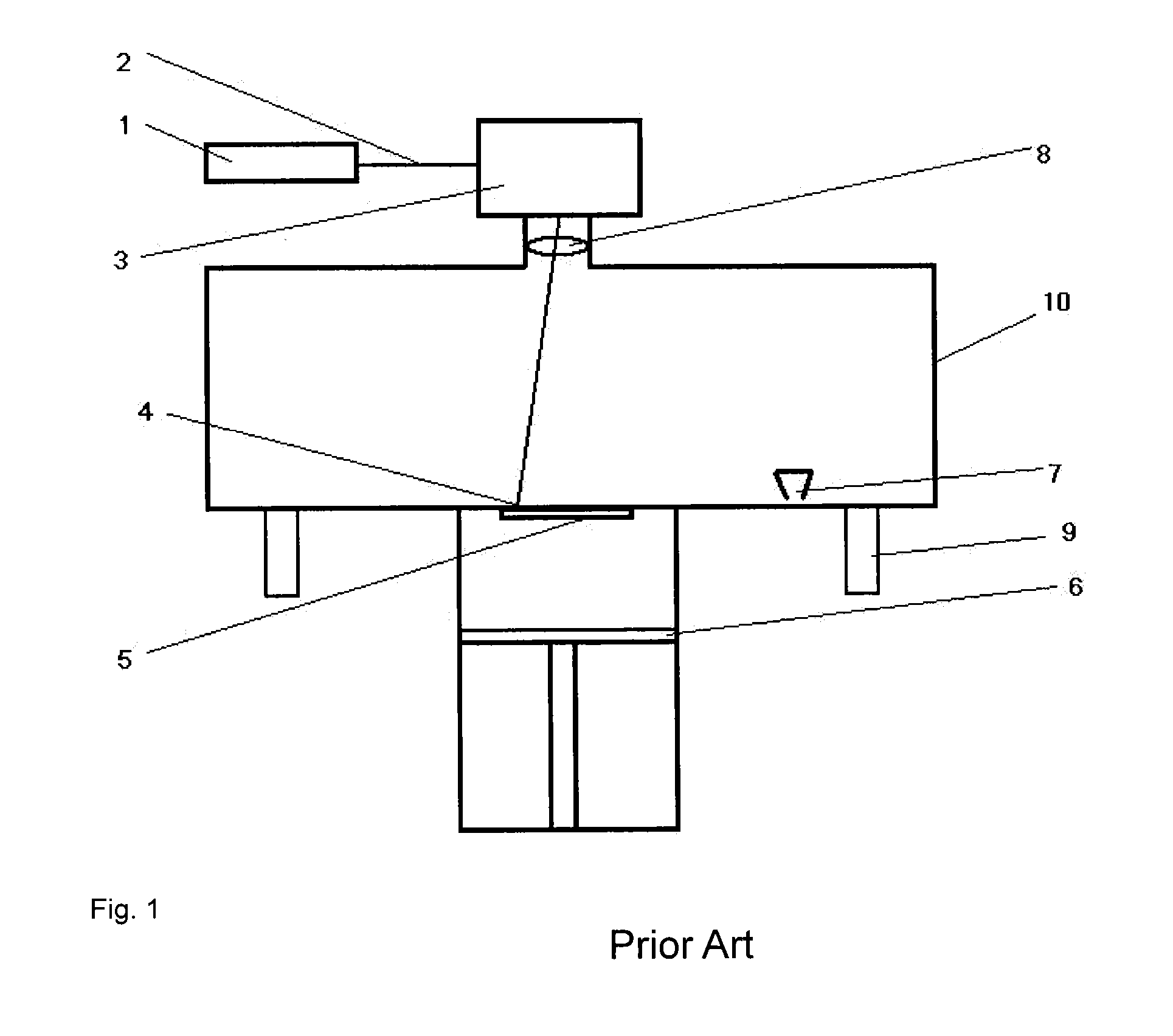
Process for melting/sintering powder particles for the layer-by-layer production of three-dimensional objects
a technology of three-dimensional objects and powder particles, which is applied in the direction of additive manufacturing processes, electric/magnetic/electromagnetic heating, manufacturing tools, etc., can solve the problems of inability to position the scanner system mirror with precision, the distance between the radiation lines the transverse speed of the energy beam cannot be increased without restriction, so as to reduce the time required and achieve the effect of reducing the quality of the object produced
- Summary
- Abstract
- Description
- Claims
- Application Information
AI Technical Summary
Benefits of technology
Problems solved by technology
Method used
Image

Examples
example 1
Not According to the Invention
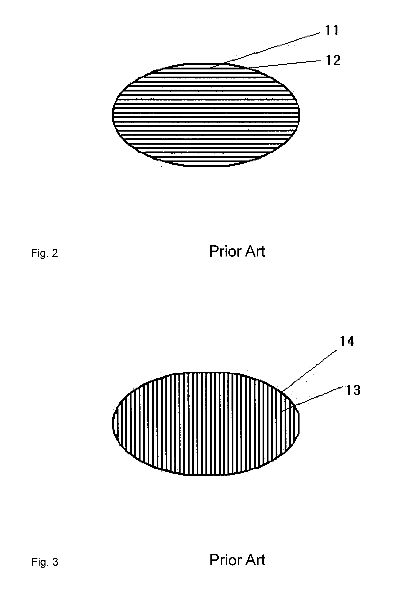
[0074]The laser used (CO2, wavelength 10.6 μm) was a Synrad Firestar t100W. A Synrad UC-2000 was used to control laser power. The power supply used was a Synrad DC-100. The scanner used was a Scanlab powerSCAN 50 mit varioSCAN 60. The energy input to the laser was 60 mJ / mm2 (laser power 20.6 W, distance between irradiation lines 0.3 mm). The laser beam was controlled in such a way that the irradiation lines were straight-line segments bounded by the edge of the area requiring hardening. The velocity in the direction of the ideally straight-line segment was 1144 mm / s. The average time required to traverse the area requiring irradiation was 30.6 seconds.
example 2
Not According to the Invention
[0075]The laser used (CO2, wavelength 10.6 μm) was a Synrad Firestar t100W. A Synrad UC-2000 was used to control laser power. The power supply used was a Synrad DC-100. The scanner used was a Scanlab powerSCAN 50 mit varioSCAN 60. The energy input to the laser was 60 mJ / mm2 (laser power 41.2 W, distance between irradiation lines 0.6 mm). The laser beam was controlled in such a way that the irradiation lines were straight-line segments bounded by the edge of the area requiring hardening. The velocity in the direction of the ideally straight-line segment was 1144 mm / s. The average time required to traverse the area requiring irradiation was 14.9 seconds.
example 3
Not According to the Invention
[0076]The laser used (CO2, wavelength 10.6 μm) was a Synrad Firestar t100W. A Synrad UC-2000 was used to control laser power. The power supply used was a Synrad DC-100. The scanner used was a Scanlab powerSCAN 50 mit varioSCAN 60. The energy input to the laser was 60 mJ / mm2 (laser power 55 W, distance between irradiation lines 0.8 mm). The laser beam was controlled in such a way that the irradiation lines were straight-line segments bounded by the edge of the area requiring hardening. The velocity in the direction of the ideally straight-line segment was 1144 mm / s. The average time required to traverse the area requiring irradiation was 11.1 seconds.
PUM
| Property | Measurement | Unit |
|---|---|---|
| Temperature | aaaaa | aaaaa |
| Temperature | aaaaa | aaaaa |
| Pressure | aaaaa | aaaaa |
Abstract
Description
Claims
Application Information