
Medical Injection Device

a technology of injection device and needle retraction, which is applied in the direction of intravenous device, infusion needle, infusion syringe, etc., can solve the problems of inaccurate delivery and/or prolonged waiting time for an injection, inconvenience for users, and inability to accurately define the time where the needle retraction actually is initiated, so as to reduce the risk of accidental sheath penetration, improve the safety of handling, and reduce the cost of the sterilizing process

Inactive Publication Date: 2013-08-22
NOVO NORDISK AS
View PDF3 Cites 78 Cited by
  • Summary
  • Abstract
  • Description
  • Claims
  • Application Information

AI Technical Summary

Benefits of technology

The invention is about a device that allows for accurate and automated needle dosing and shielding. When using this device, the needle only needs to be inserted into the skin for a short time, resulting in improved dosing accuracy. The device also includes sterilizing compartments for each needle, which prevents accidental sheath penetration and improves safety during handling. Overall, this invention reduces the risk of accidental sheath penetration, improves safety and reduces the cost of sterilization.

Problems solved by technology

As identified in WO 03 / 097133, an injection device of the above type, have a problem with dosage delivery due to length tolerances of the syringe and due to the exact trigger point for triggering of the needle retraction being very much dependent on the length of the syringe.
However, due to the damping system is initiated upon the initial actuation of the device, the point in time where the needle retraction actually is initiated is not well defined relative to the point in time where the piston impacts the internal end walls of the syringe.
This may still lead to inaccurate delivery and / or prolonged waiting time for an administration to be completed.
This phenomenon is causing some inconvenience for the user.
Both solutions result in unnecessary complex devices.

Method used


Image

  • Medical Injection Device
  • Medical Injection Device
  • Medical Injection Device

Examples


first embodiment

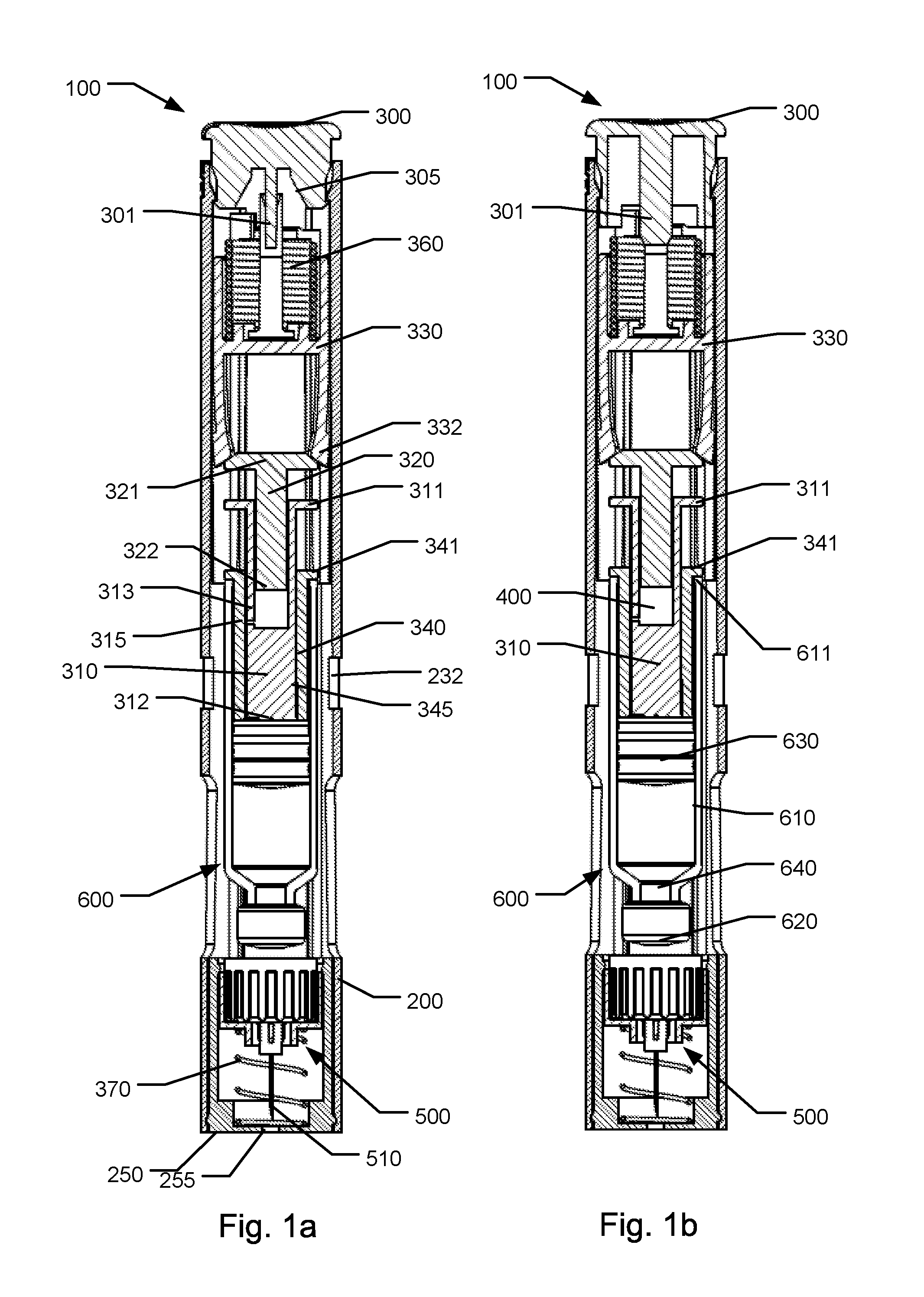
[0086]FIG. 1a shows a front sectional view of an injection device 100 according to the first aspect of the invention, in an initial storage state wherein a needle cannula of the device is in a shielded state,

[0087]FIG. 1b shows a front sectional view of the first embodiment in a state wherein an activator button has been turned for unlocking the activator button,

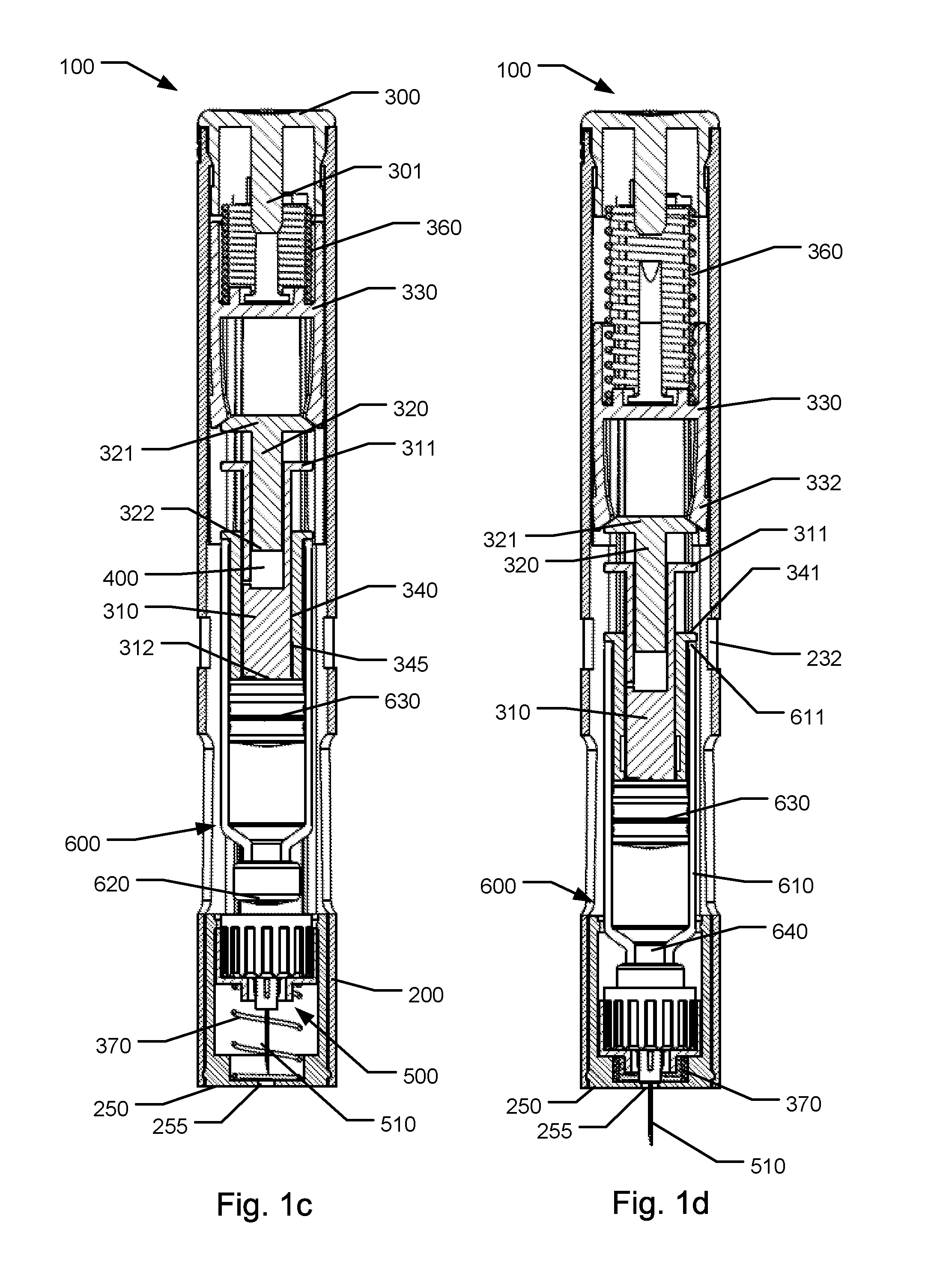
[0088]FIG. 1c shows a front sectional view of the first embodiment in a state wherein the activator button has been depressed,

[0089]FIG. 1d shows a front sectional view of the first embodiment in a state wherein a needle cannula fully protrudes from a needle shielding portion,

[0090]FIG. 1e shows a front sectional view of the first embodiment in a state wherein a cartridge has been moved relative to the needle cannula for establishing fluid communication,

[0091]FIG. 1f shows a front sectional view of the first embodiment in an end of stroke condition for a piston of the cartridge at the initial state of a damper,

[0092]FIG. 1g ...

second embodiment

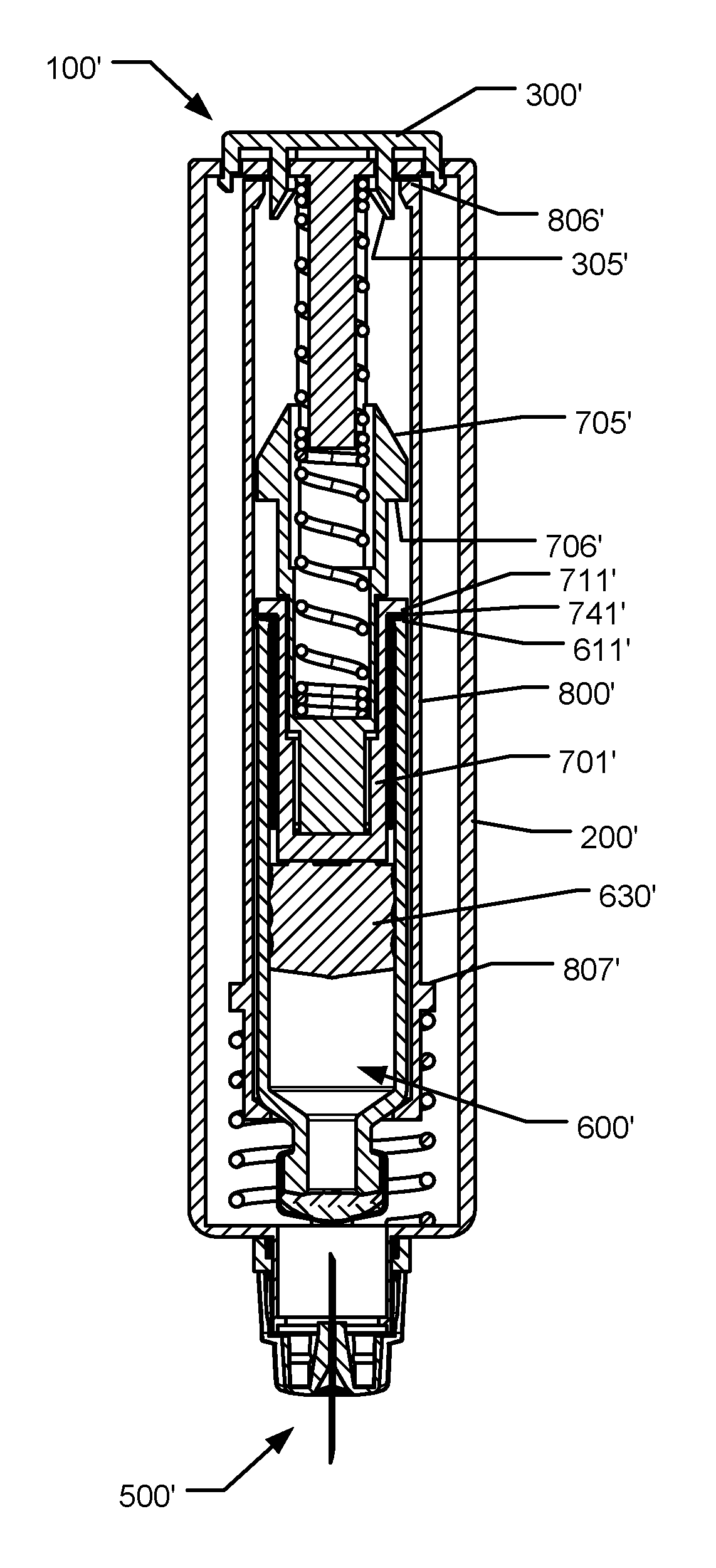
[0095]FIG. 3 show a detailed view of a needle assembly according to the invention,

[0096]FIG. 4a shows a detailed front sectional view of the damper of the first embodiment in the state as shown in FIG. 1f,

[0097]FIG. 4b shows a detailed front sectional view of the damper of the first embodiment in the state as shown in FIG. 1g,

third embodiment

[0098]FIG. 5a through 5h show cross-sectional views of an injection device in various different states during an injection process,


PUM


Abstract

The present invention relates to injection devices for injecting a medicament from a cartridge (600) through a needle cannula (510). The injection device (100) includes an actuator (330, 360) for driving a piston driver (310) and includes an end of stroke limiter (341, 611). When the piston driver (310) is arrested by the end of stroke limiter (341, 611) a shielding driver (370) is automatically triggered to actively shift the needle cannula (510) into a shielded state. The injection device may include a fluid dispensing interruption mechanism that automatically interrupts fluid flow when the piston driver has moved a predetermined stroke length. The injection device may also include a single pre-stressed spring acting exclusively in a linear compression mode or exclusively in a torsion mode and adapted to sequentially drive the device to enable fully automatic operation. The invention also relates to a method of sterilizing a needle cannula assembly.

Description

FIELD OF THE INVENTION[0001]The present invention relates to injection devices for injecting a medicament. In particular the present invention relates to injection devices for injecting a medicament from a held cartridge and improvements relating to the performance of such injection devices.BACKGROUND OF THE INVENTION[0002]In relation to some diseases patients must inject a medicament on a regular basis such as once weekly, once daily or even a plurality of times each day. In order to help patients overcome fear of needles, fully automatic injection devices have been developed that makes the use of an injection device as simple as possible. Such devices are typically designed such that a user shall position the injection device onto the injection site and activate the device. Such activation causes the device to insert a needle into the skin, eject a dose of the medicament and subsequently move the needle into a shielded position.[0003]An example of such a device is shown in EP51647...

Claims


Application Information

Patent Timeline
Patent Type & Authority Applications(United States)
IPC IPC(8): A61M5/315A61M5/24A61M5/32
CPCA61M5/001A61M5/002A61M5/2033A61M5/326A61M2005/206A61M5/3202A61M2005/247A61M2005/3118A61M2005/31518A61M5/2466A61M5/31501A61M2005/2086
Inventor MARKUSSEN, TOM HEDEMICHELSEN, FREDDY VERNERRADMER, BOWINTHER, KNUD SKIFTERGJOEDESEN, CLAUS URUPNIELSEN, CHRISTIAN HOEJRISPETERSEN, MARTIN MAJDALLWINDUM, JESPER PETER
Owner NOVO NORDISK AS
Learn More