
Energy control method for energy management system

a technology of energy management system and energy control method, which is applied in the direction of process and machine control, greenhouse gas reduction, instruments, etc., can solve the problems of inability to cope with sudden increase in demand, inability to provide information, and inability to meet the requirements of energy saving effect,

Inactive Publication Date: 2013-08-22
ELECTRONICS & TELECOMM RES INST
View PDF11 Cites 27 Cited by
  • Summary
  • Abstract
  • Description
  • Claims
  • Application Information

AI Technical Summary

Benefits of technology

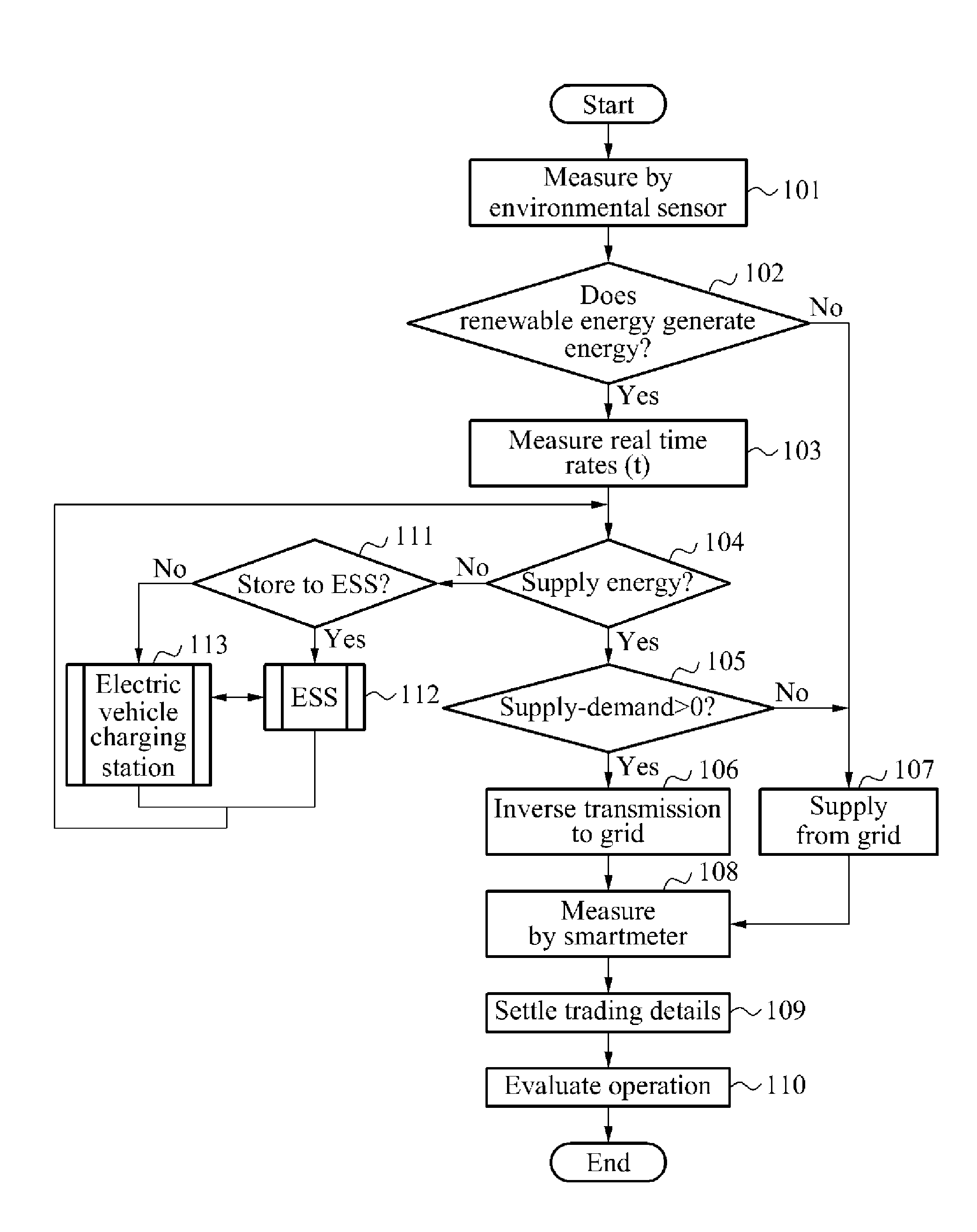
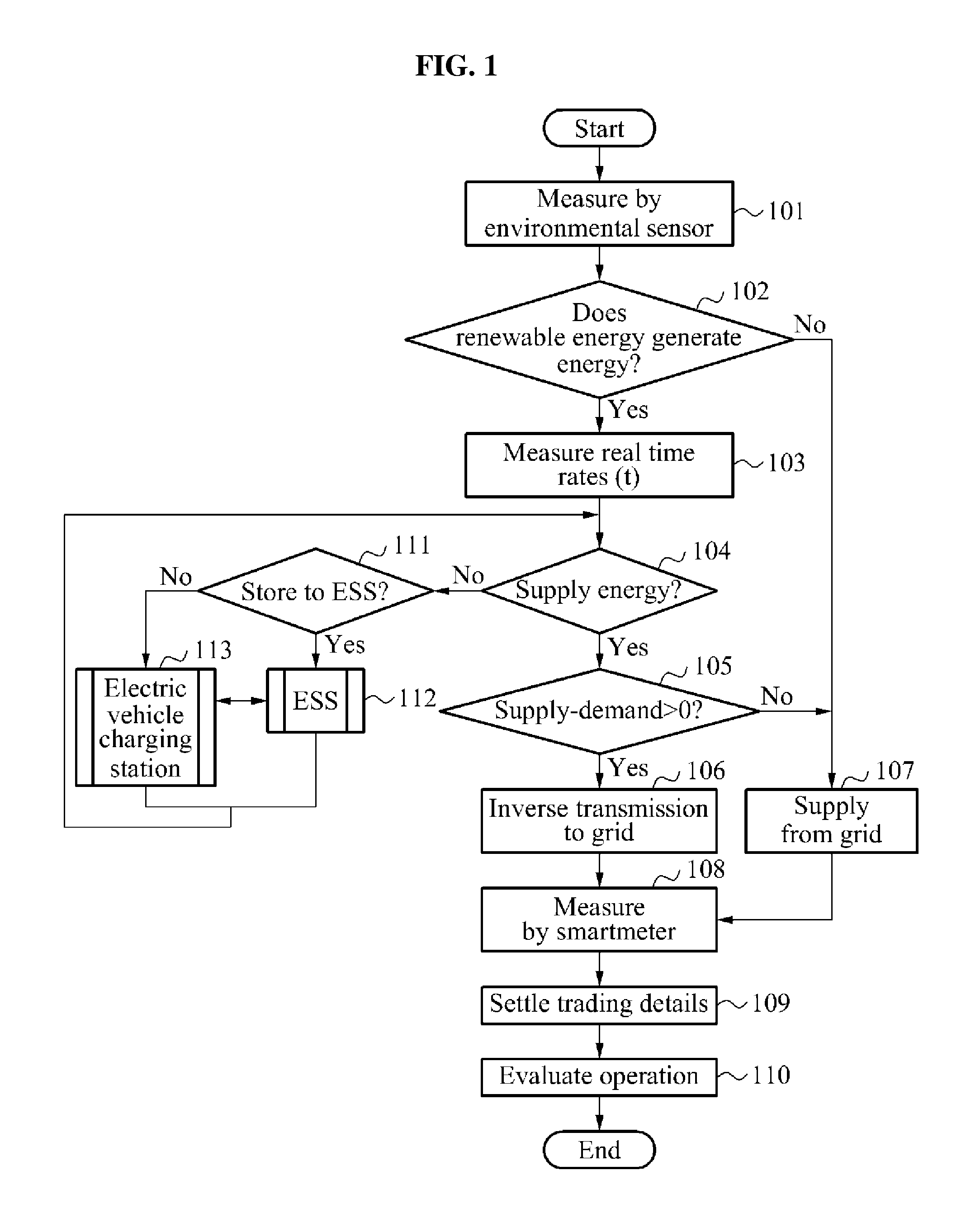
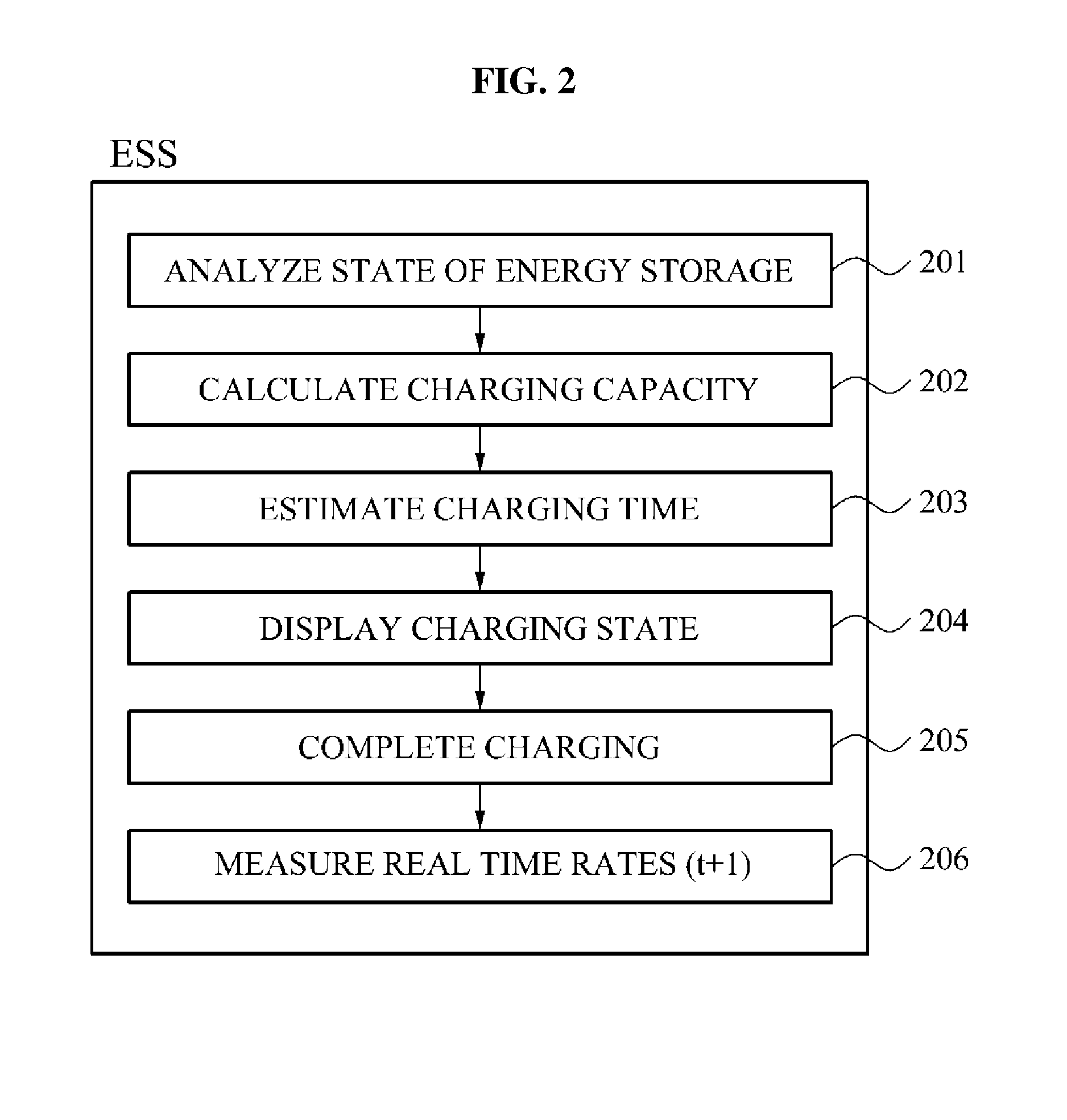
The present invention provides an energy control method for managing the charging and discharging state of energy supplied by a renewable energy system, separately by an electric vehicle charging station and an energy storage system. The method also enables energy trading and provides information and operation evaluation functions with respect to settlement details caused by various procedures regarding energy supply and demand. The technical effects include optimizing energy utilization, reducing energy wastage, and promoting energy trading.

Problems solved by technology

However, according to such a passive-type energy saving technology, it is difficult to cope with a sudden increase in demand since real time reflection of the price information is almost infeasible.
Also, the energy saving effect may not be satisfactory.
However, according to the market research related to the smart appliances, most consumers are afraid that their private information such as information on their own home appliances may be exposed to the outside due to the direct load control, and therefore want final control of the appliances to be performed by themselves.
The foregoing technologies do not verify a procedure of confirming an access trouble through association with the HEMS.
Although technologies regarding the storage system and the charging station are under development, functions of a home energy management system (HEMS) to collectively manage and control energy supply are absent.

Method used


Image

  • Energy control method for energy management system
  • Energy control method for energy management system
  • Energy control method for energy management system

Examples


Embodiment Construction

[0024]According to an embodiment of the present invention, real time rates measurement provided by an electric power company may be achieved through construction of renewable energy facilities and storage system, two-way communication, and advanced metering infrastructure. Therefore, a consumer may store energy generated by a renewable energy power supply in a home storage system in case of a light load, or use the energy in case of a peak load, by participating in demand response (DR). Thus, energy use efficiency may be optimized. The consumer may construct an energy storage system (ESS) and an electric vehicle charging station, may store or supply energy to any one of the ESS and the electric vehicle charging station as desired by selecting a storage mode of a home energy management system (HEMS), and may sell surplus energy through inverse power transmission to the electric power company in association with a grid or receive shortage of energy from the grid. Accordingly, the embo...


PUM


Abstract

An energy control method for an energy management system provides an operation plan for the energy management system for monitoring and controlling an energy charging and discharging state according to an energy storage type, since energy self-sufficiency at home is enabled through association between an energy storage system (ESS) such as an electric vehicle charging station and home as a renewable energy power supply in the form of a distributed energy resource (DER) is constructed at home. The energy control method adds functions of a home energy management system (HEMS) managing and controlling a renewable energy power supply, the ESS, and the electric vehicle charging station that may be constructed at home afterwards, thereby providing consumers with a control order of various facilities not considered before. Therefore, information on settlements caused by energy supply and demand procedures and energy trading details and management evaluation functions may be provided.

Description

CROSS-REFERENCE TO RELATED APPLICATION[0001]This application claims the benefit of Korean Patent Application No. 10-2012-0016193, filed on Feb. 17, 2012, in the Korean Intellectual Property Office, the disclosure of which is incorporated herein by reference.BACKGROUND[0002]1. Field of the Invention[0003]The present invention relates to an energy control method for an energy management system that provides an operation plan for the energy management system for monitoring and controlling an energy charging and discharging state according to an energy storage type, since energy self-sufficiency at home is enabled through association between an energy storage system (ESS) such as an electric vehicle charging station and home as a renewable energy power supply in the form of a distributed energy resource (DER) is constructed at home.[0004]2. Description of the Related Art[0005]A conventional energy saving technology has been developed and commercialized in the form of an energy-saving mo...

Claims


Application Information

Patent Timeline
IPC IPC(8): G06Q50/06
CPCG06Q50/06Y02T90/168Y04S30/12H02J3/008H02J3/382H02J13/0006Y02E40/72Y04S10/123Y04S10/126Y04S20/221Y04S20/224Y04S50/10Y02E60/721Y02B70/3216H02J3/322H02J2300/20H02J3/381H02J3/004Y02E70/30Y02B70/30Y02E60/00Y02T90/167Y04S20/222Y04S30/14Y02B70/3225H02J13/00002H02J3/36H02J7/00Y02E40/70
Inventor LEE, JEONG INLEE, IL WOO
Owner ELECTRONICS & TELECOMM RES INST
Learn More