Apparatus for Establishing a Paver Surface Over a Subsurface

Inactive Publication Date: 2013-08-29
TABIBNIA RAMIN
View PDF22 Cites 34 Cited by
  • Summary
  • Abstract
  • Description
  • Claims
  • Application Information

AI Technical Summary

Benefits of technology

[0013]It is an object of the present application to disclose apparatus and related methods for facilitating the elevated and leveled placement of a paver array onto a subsurface with even and uniform spacing and orientation in a manner that alleviates the problems associated with apparatus heretofore known for the same purpose. In particu

Problems solved by technology

While such apparatus are suitable for spacing square pavers, the subject apparatus are not adequate since non-square pavers are often used when constructing a paver surface.
Furthermore, shifting the entire apparatus to orient the paver array may be tedious.
However, these apparatus designs are still limited and may involve tedious attachment methods.
While such manner of paver surface elevation may be suitable for incremental increases in surface levels, stacking apparatus in the described manner is limiting of the ultimate height to which the stack may raise the surface since the base apparatus features the same dimensions as the top-most apparatus in the stack.
Stacking apparatus to increase paver surface elevation is also limited because the exact adjustment of paver surface height depends on the thickness of the individual apparatus within the stack (i.e., exact adjustment of paver surface height requires multiple apparatus of different thickness or the shaving-off of apparatus thickness).
Screw-jack mechanisms are not completely satisfactory for raising the height of a paver surface since screw jack mechanisms are expensive to fabricate and the surface height cannot be increased beyond two-times the apparatus thickness without the addition of multiple components.
A telescoping pedestal is unsatisfactory because it requires the manufacture of different sized levels or complex assembly methods (see e.g., U.S. Pat. No. 4,570,397 wherein a fill is added).
Central riser designs are not adequate because accommodations cannot be made for inaccurate measurements or unanticipated changes in desired paver heights.
Further, central riser designs are inadequate because such designs often require the existence of multiple distinct components for supporting the central riser, including base and cap members, which are expensive and tedious to fabricate due to the requirement of differing molds or other fabrication tools.
Twist slope manipulation has not b

Method used


Image

  • Apparatus for Establishing a Paver Surface Over a Subsurface
  • Apparatus for Establishing a Paver Surface Over a Subsurface
  • Apparatus for Establishing a Paver Surface Over a Subsurface

Examples


first embodiment

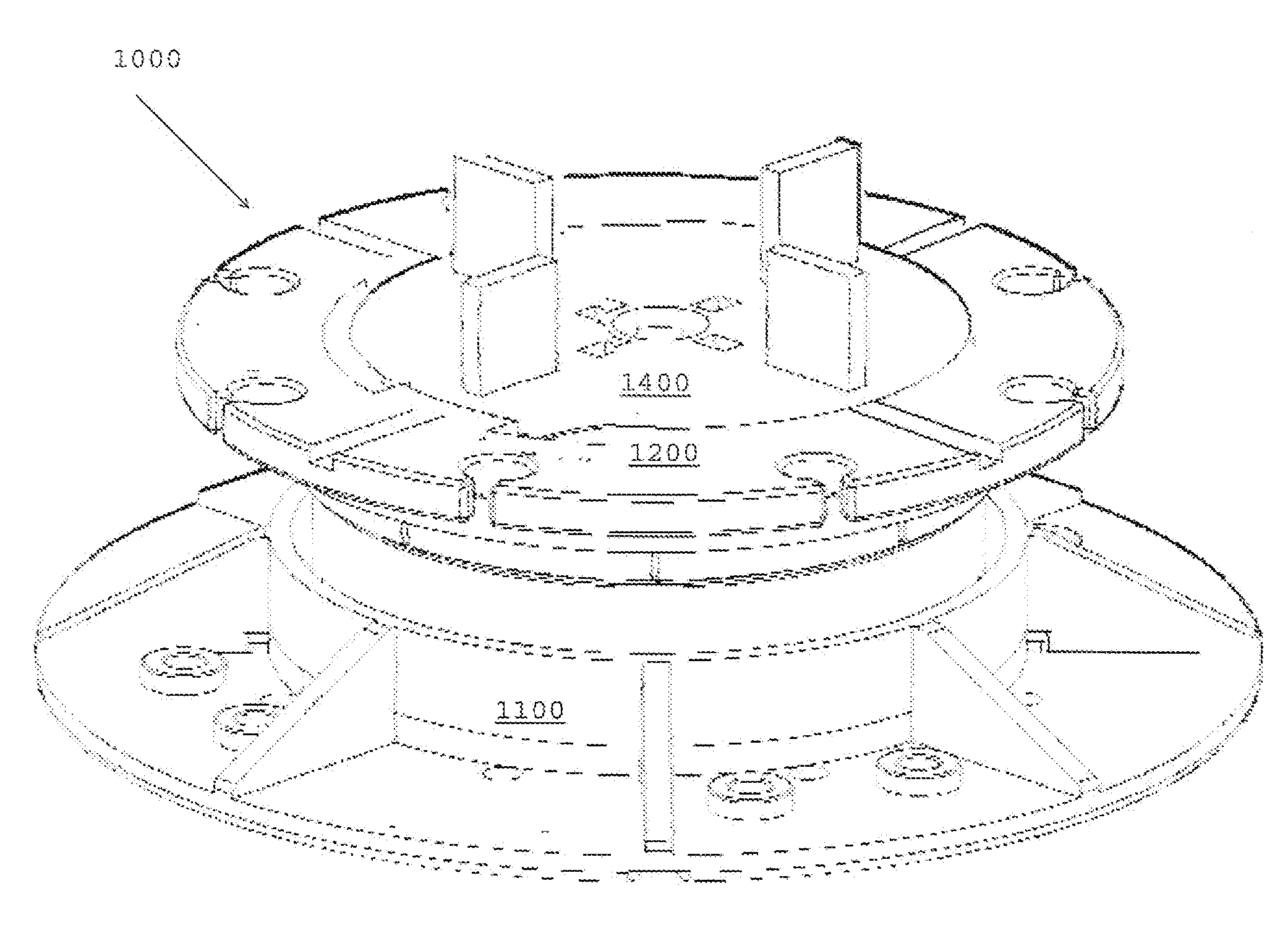
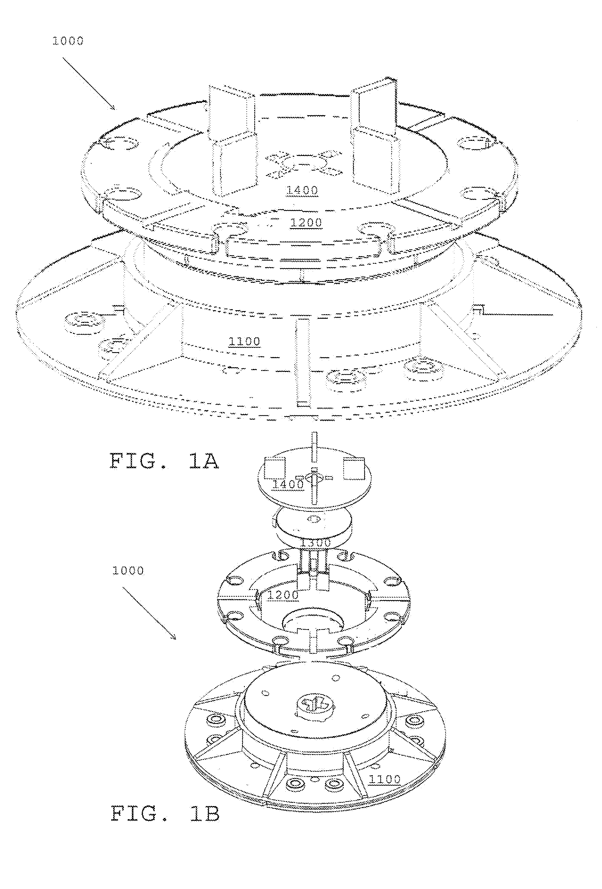
[0093]FIGS. 1A and 1B depict an assembly 1000 for facilitating the elevated and leveled placement of a paver array onto a substrate. FIG. 1A is a perspective view of the assembly1000 and FIG. 1B is an exploded view of the same. As seen in the figures the assembly 1000 comprises: a base 1100; a cap 1200; a pin 1300; and, a tile spacer 1400.

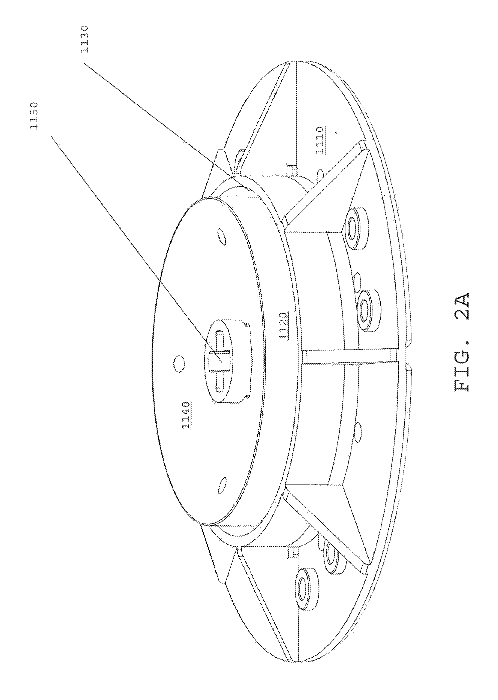
[0094]FIGS. 2A through 2E depict different views of a preferable embodiment of the base 1100 component of the apparatus 1000 depicted in FIGS. 1A and 1B. Specifically, FIGS. 2A through 2E respectively depict a top perspective, bottom perspective, top plan, bottom plan, and side profile view of the base 1100. As can be seen in the referenced drawings, the base is generally a truncated cylinder and may comprise: a foot 1110; a support cylinder 1120; a riser socket 1130 around the cylinder; a concave surface 1140 defining the top of the cylinder 1120; and a key socket 1150 through the concave surface 1140 along the axis of the cylinder 1120.

[0095]FIGS...

third embodiment

[0114]FIGS. 14 and 15 depict an assembly 3000 for facilitating the elevated and leveled placement of a paver array onto a substrate. FIG. 14 is a side view of the assembly 3000 and FIG. 15 is an exploded view of the same. As seen in the figures the assembly 3000 comprises: a base 3100; a threaded insert 3500, and a cap 3200.

[0115]FIGS. 16A through 16D depict different views of a preferable embodiment of the base 3100 component of the apparatus 3000 depicted in FIGS. 14 and 15. Specifically, FIGS. 16A through 16D respectively depict a top perspective, top plan, bottom plan, and side profile view of the base 3100. As can be seen in the referenced drawings, the base is generally a truncated cylinder and may comprise: a foot 3110; a femininely threaded support cylinder 3120; and, a riser socket 3130 around the cylinder.

[0116]FIGS. 17A through 17E depict different views of a preferable embodiment of the cap 3200 component of the apparatus 3000 depicted in FIGS. 14 and 15. Specifically, F...


PUM


Abstract

Disclosed is an improved assembly for facilitating the elevated and leveled placement of a paver surface. Yet further disclosed are related methods of using the assembly.

Description

CROSS-REFERENCE TO RELATED APPLICATIONS[0001]This application is a continuation in part of U.S. patent application Ser. No. 12 / 732,755 (filed Mar. 26, 2010) entitled “Apparatus for establishing a paver over a subsurface” and said patent application is hereby incorporated by reference in its entirety.STATEMENT REGARDING FEDERALLY SPONSORED RESEARCH OR DEVELOPMENT[0002]Not applicable.BACKGROUND OF THE INVENTION[0003]1. Field of Invention[0004]The present application is in the field of methods and apparatus for establishing a paver surface. The present application is also in the field of methods and apparatus for elevating a paver surface with respect to a subsurface and / or compensating for the slope of the subsurface.[0005]2. Background of the Invention[0006]Frequently, it is desirable to establish a surface above a subsurface. For instance, a surface may be established over a subsurface to, in effect, adjust the aesthetic and / or physical properties of the subsurface. Commonly, such a...

Claims


Application Information

Patent Timeline
IPC IPC(8): E04F15/024
CPCE04F15/02464E04F15/02482E04D11/007E04F15/02452
Inventor TABIBNIA, RAMIN
Owner TABIBNIA RAMIN
Why Eureka
Try Eureka