
Variable intake device of engine

a variable intake device and engine technology, applied in the direction of combustion-air/fuel-air treatment, air cleaner and silencer combination, charge feed system, etc., can solve the problems of increasing the diameter of the engine, increasing the intake noise, and reducing the commercial value of the vehicle, so as to increase the output of the engine, increase the weight, and reduce the effect of intake nois

Inactive Publication Date: 2013-08-29
HYUNDAI MOTOR CO LTD
View PDF8 Cites 4 Cited by
  • Summary
  • Abstract
  • Description
  • Claims
  • Application Information

AI Technical Summary

Benefits of technology

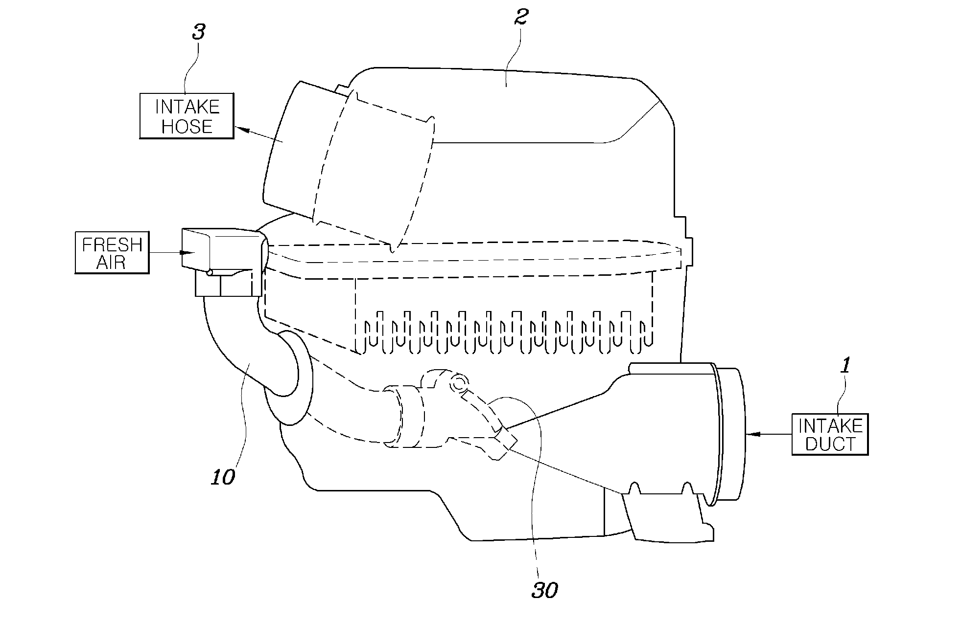
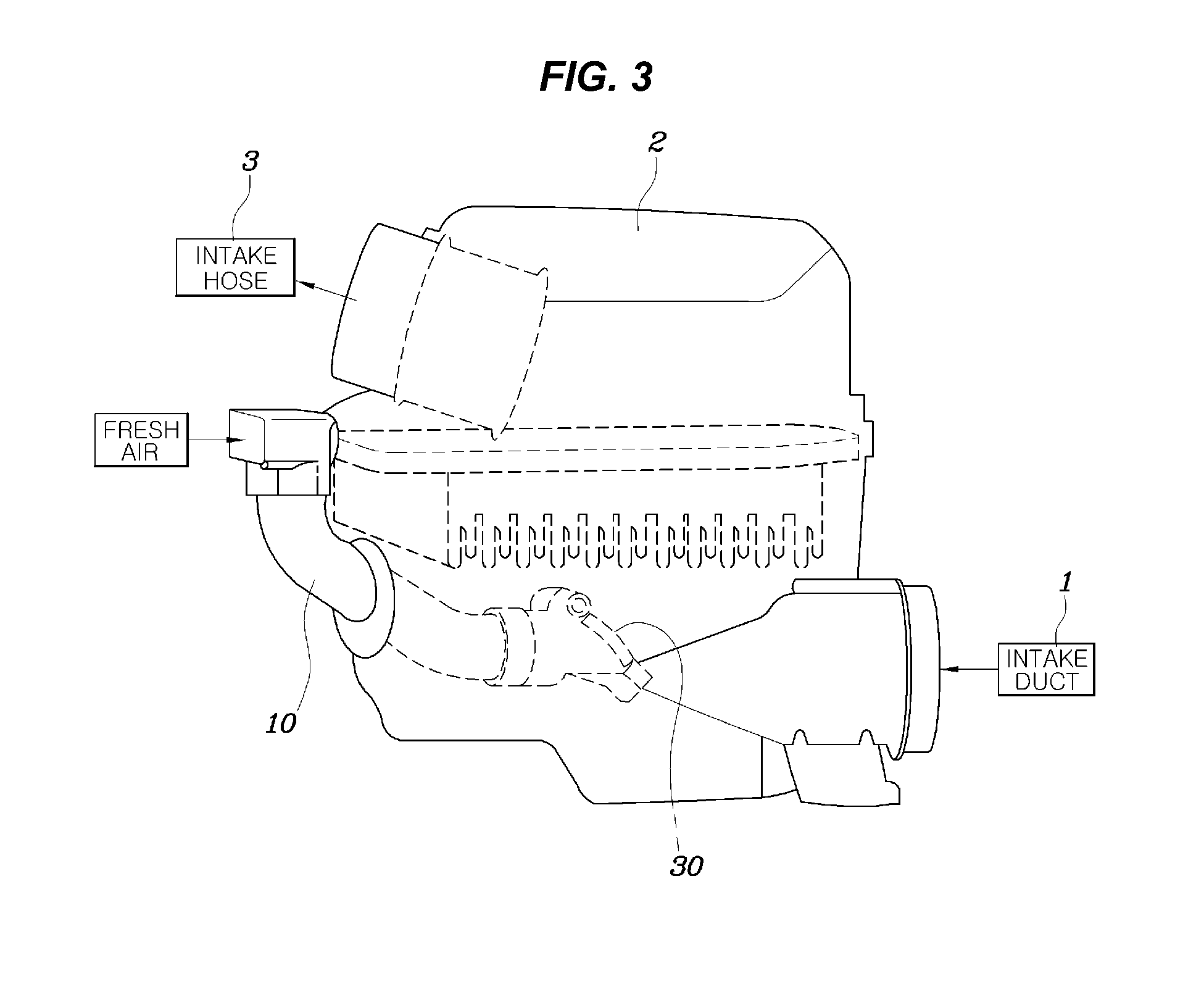
The present invention provides a variable intake device for an engine that can adjust the amount of air supplied into a combustion chamber in accordance with the RPM of an engine. This allows for more air to be supplied into the combustion chamber when the engine operates with high RPM, resulting in increased output without changing the layout of the engine room or increasing manufacturing costs or intake noise. The device includes an auxiliary intake duct made of porous non-woven fabric to reduce intake noise, an intake hose to direct air from the air cleaner to the combustion chamber, and a resonator to reduce intake noise. Additionally, a valve pad member is fitted on an outer circumference of the valve plate to seal a gap between the auxiliary intake duct and the valve plate to remove operational noise of the valve plate.

Problems solved by technology

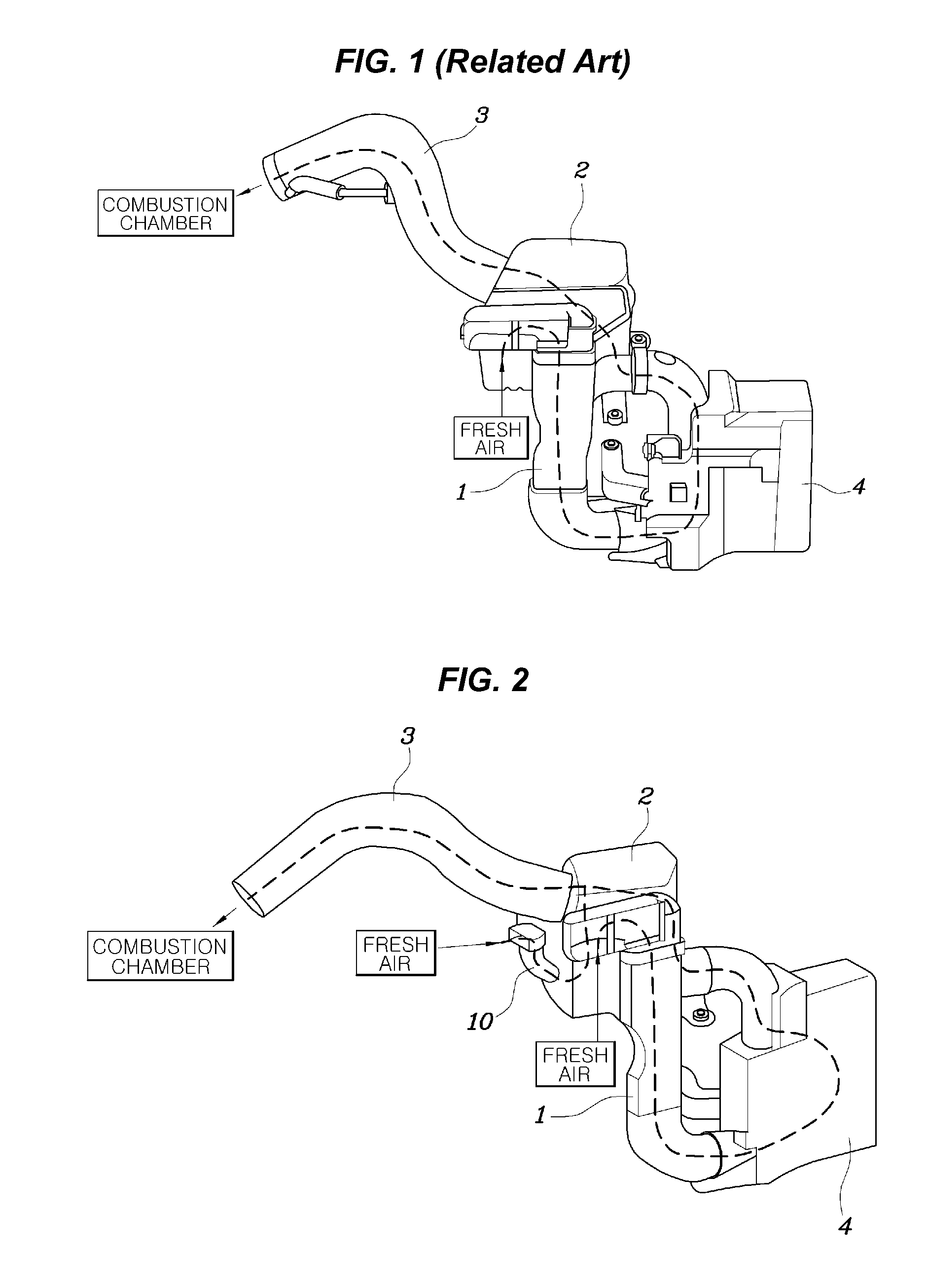
However, there is a limit in increasing the diameter, that is, the cross-sectional area of the intake duct 1 or the intake hose 3 due to a small layout of the engine room, and when the length of the intake duct 1 or the intake hose 32 is made short, the combustion noise of the engine is easily transmitted to the outside through the intake system so that the intake noise increases, and thus, the commercial value of a vehicle decreases.
Further, there is a method of increasing the number of the resonators 4 or increasing the capacity thereof in order to reduce the intake noise after decreasing the length of the intake duct 1 or the intake hose 3, but the weight and the manufacturing cost increase in this case.

Method used


Image

  • Variable intake device of engine
  • Variable intake device of engine
  • Variable intake device of engine

Examples


Embodiment Construction

[0034]Reference will now be made in detail to various embodiments of the present invention(s), examples of which are illustrated in the accompanying drawings and described below. While the invention(s) will be described in conjunction with exemplary embodiments, it will be understood that the present description is not intended to limit the invention(s) to those exemplary embodiments. On the contrary, the invention(s) is / are intended to cover not only the exemplary embodiments, but also various alternatives, modifications, equivalents and other embodiments, which may be included within the spirit and scope of the invention as defined by the appended claims.

[0035]Hereinafter reference will now be made in detail to various embodiments of the present invention, examples of which are illustrated in the accompanying drawings and described below.

[0036]A variable intake device of an engine according to an exemplary embodiment of the present invention is described hereafter with reference t...


PUM


Abstract

A variable intake device of an engine may include an auxiliary intake duct that may be disposed with one end thereof inserted inside an air cleaner and sucks air, and a magnetic variable valve that may be disposed at the one end of the auxiliary intake duct positioned inside the air cleaner to selectively open or close the auxiliary intake duct so that as intake negative pressure increases, an open angle of the magnetic variable valve increases.

Description

CROSS-REFERENCE TO RELATED APPLICATION[0001]The present application claims priority to Korean Patent Application No. 10-2012-0021075 filed Feb. 29, 2012 the entire contents of which is incorporated herein for all purposes by this reference.BACKGROUND OF THE INVENTION[0002]1. Field of the Invention[0003]The present disclosure relates to a variable intake device of an engine. More particularly, it relates to a variable intake device of an engine that can adjust the amount of air supplied into a combustion chamber in accordance with the RPM of the engine.[0004]2. Description of Related Art[0005]As shown in FIG. 1, in general, fresh air (external air) is supplied into the combustion chamber of an engine sequentially through an intake duct 1, an air cleaner 2, and an intake hose 3 in the intake stroke of the engine piston, and the intake duct 1 is equipped with a resonator 4 for reducing intake noise.[0006]In particularly, a lager amount of fresh air should be supplied into the combustio...

Claims


Application Information

Patent Timeline
Patent Type & Authority Applications(United States)
IPC IPC(8): F02M35/10
CPCF02M35/14F02M35/082F02M35/024F02M35/10308F02M35/104F02B27/02
Inventor YUN, TAE MINKIM, SE IL
Owner HYUNDAI MOTOR CO LTD
Learn More