Fire Hydrant Marker Repeater

a repeater and fire hydrant technology, applied in the field of remote monitoring systems, can solve the problems of inability to place a transceiver inside the hydrant, limited locations where water utilities can deploy such equipment, and additional equipmen

Inactive Publication Date: 2013-08-29
AXIOMETRIC
View PDF3 Cites 5 Cited by
  • Summary
  • Abstract
  • Description
  • Claims
  • Application Information

AI Technical Summary

Problems solved by technology

Because the geographic regions served by water utilities are often large, their radio systems frequently require additional equipment to help carry the radio signals over large distances.
Unfortunately, water utilities have limited locations where they can deploy such equipment; locations with power are often limited to large installations such as pump / lift stations and large water storage towers.
Unfortunately, fire hydrants are typically metal and radio frequencies cannot pass through metal easily making placement of a transceiver inside a hydrant unfeasible.
Moreover, transceivers attached to the outside of a fire hydrant are subject to theft and abuse and they remain relatively low to the ground where their antennas are limited in range.
However, these systems are simply used to locate a fire hydrant and do not typically allow for receiving information pertaining to the water line servicing that fire hydrant or surrounding areas.
However, while useful for the purpose for which it was intended, this system only passively generates a locating signal.
Moreover, this system only provides a flashing light to alert firemen attempting to locate a hidden fire hydrant during an emergency response.
However, if the fire hydrant is covered by significant amounts of snow, which often happens as a result of snow drifts and snow plows pushing snow over a fire hydrant, then the flashing light will not be visible.
Moreover, such a system does not allow a water utility company to monitor or remotely determine the location of a fire hydrant or water utility line.
Because such a sub-system is exposed on the outside of the fire hydrant, it is prone to tampering, weathering, destruction, and other malfunctions causing operational deficiencies.
Unfortunately, these solutions are limited due to their small size which offers very limited battery power and requires a very small and low antenna, which reduces signal transmission.

Method used


Image

  • Fire Hydrant Marker Repeater
  • Fire Hydrant Marker Repeater
  • Fire Hydrant Marker Repeater

Examples


Embodiment Construction

[0015]The embodiments herein and the various features and advantageous details thereof are explained more fully with reference to the non-limiting embodiments that are illustrated in the accompanying drawings and detailed in the following description. Descriptions of well-known components and processing techniques are omitted so as to not unnecessarily obscure the embodiments herein. The examples used herein are intended merely to facilitate an understanding of ways in which the embodiments herein may be practiced and to further enable those of skill in the art to practice the embodiments herein.

[0016]Accordingly, the examples should not be construed as limiting the scope of the embodiments herein.

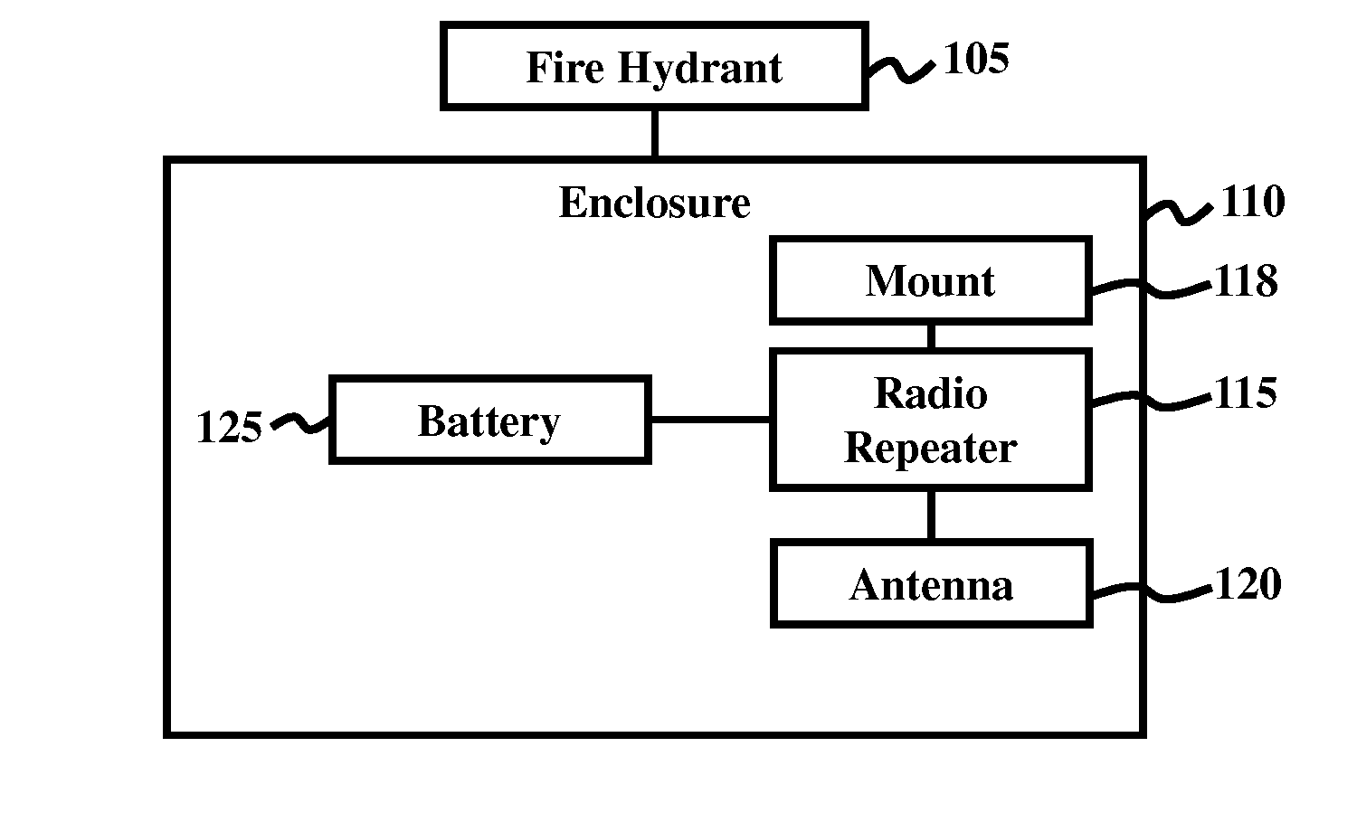
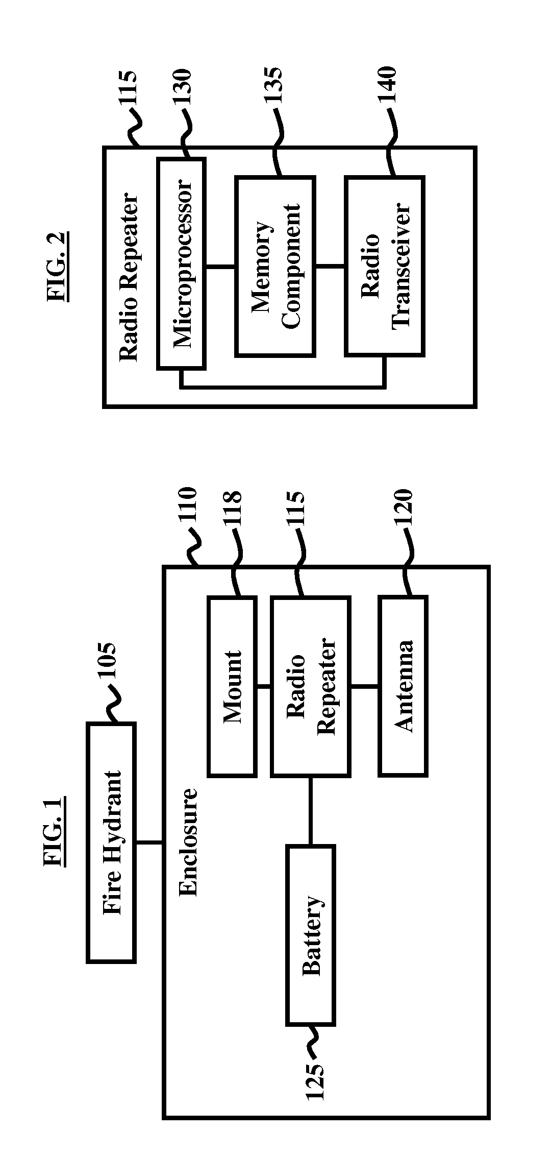
[0017]The embodiments herein provide a repeater device used with water utility systems. Referring now to the drawings, and more particularly to FIGS. 1 through 3, where similar reference characters denote corresponding features consistently throughout the figures, there are shown preferred...


PUM


Abstract

A system includes a fire hydrant; a gain antenna operatively connected to the fire hydrant; at least one battery operatively connected to the fire hydrant; and a radio repeater operatively connected to the fire hydrant. The gain antenna includes any of a vertical monopole and a dipole antenna. The battery may include a lithium thionyl battery. The battery powers the radio repeater. The radio repeater includes a microprocessor; a memory component; and a radio transceiver. The system may further include a non-metallic enclosure that houses the radio repeater. The gain antenna may be operatively connected to the radio repeater inside the non-metallic enclosure. The radio repeater may further include an electronic voltage reference source that provides a stable voltage reference level that is lower than a lowest battery operating voltage of the at least one battery.

Description

BACKGROUND[0001]1. Technical Field[0002]The embodiments herein generally relate to remote monitoring systems, and, more particularly, systems used to electronically monitor utility devices.[0003]2. Description of the Related Art[0004]Water utilities frequently deploy radio-based monitoring and control systems for a variety of purposes such as monitoring water pressures, storage tanks, effluent levels, and water metering / billing. Because the geographic regions served by water utilities are often large, their radio systems frequently require additional equipment to help carry the radio signals over large distances. Unfortunately, water utilities have limited locations where they can deploy such equipment; locations with power are often limited to large installations such as pump / lift stations and large water storage towers.[0005]Water utilities generally have a large number of fire hydrants dispersed across their service region. The utilities typically own the hydrants and an easement...

Claims


Application Information

Patent Timeline
Patent Type & Authority Applications(United States)
IPC IPC(8): H01Q1/12H01Q1/42
CPCH01Q1/225
Inventor ALBERT, DAVID A.
Owner AXIOMETRIC
Why Eureka
Try Eureka