Camera device, image processing system, image processing method and image processing program

Active Publication Date: 2013-08-29
PANASONIC CORP
View PDF0 Cites 28 Cited by
  • Summary
  • Abstract
  • Description
  • Claims
  • Application Information

AI Technical Summary

Benefits of technology

[0008]The present invention has been accomplished under the above circumstances. The objective of the present invention is to provide a camera device capable of

Problems solved by technology

However, in the conventional system, when the imaging object passes nearly just under the camera, the orientation of the imaging object displayed in the

Method used


Image

  • Camera device, image processing system, image processing method and image processing program
  • Camera device, image processing system, image processing method and image processing program
  • Camera device, image processing system, image processing method and image processing program

Examples


first embodiment

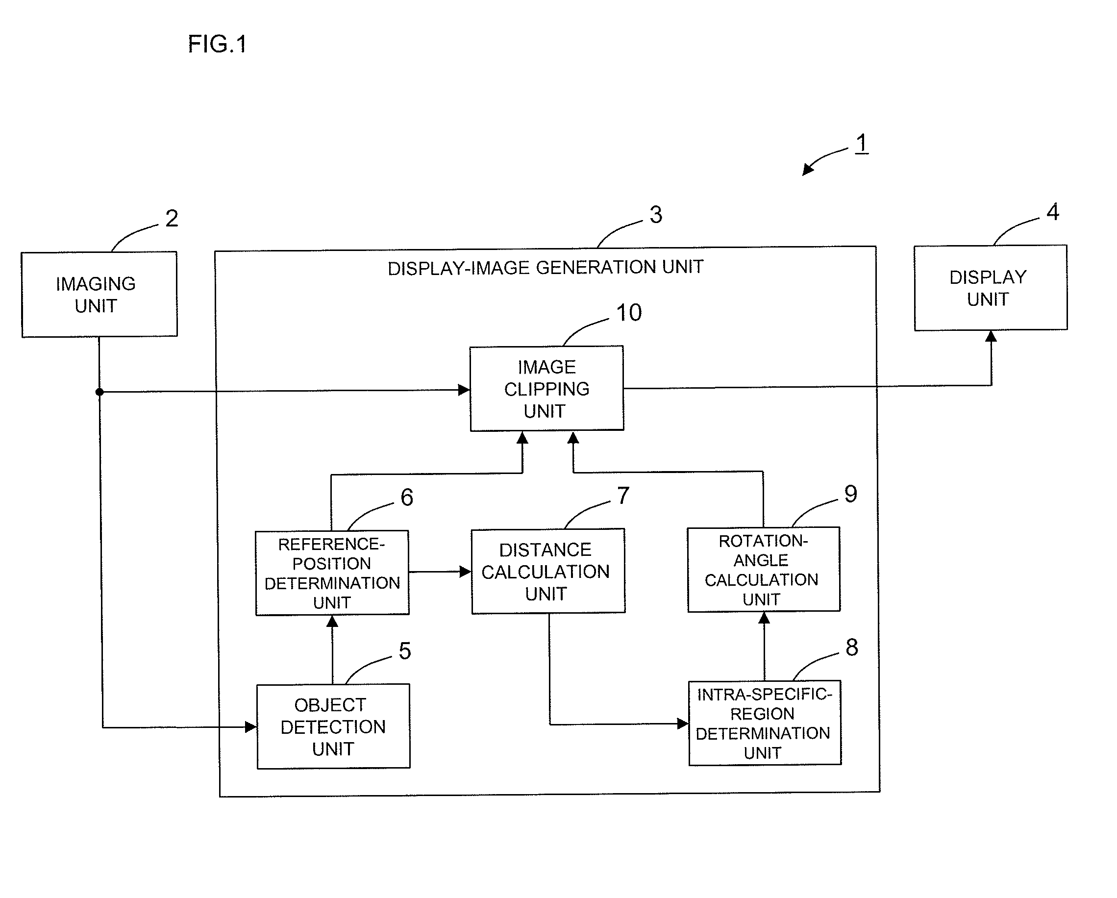
[0047]A configuration of a camera device in accordance with a first embodiment of the present invention will be described with reference to drawings. FIG. 1 is a block diagram of the camera device in accordance with the first embodiment of the present invention. As shown in FIG. 1, a camera device 1 includes an imaging unit 2 capturing an image (imaging area image) in an imaging area, a display-image generation unit 3 providing predetermined image processing (described later) to the imaging by the imaging unit 2 to generate a display image, and a display unit 4 displaying the display image.

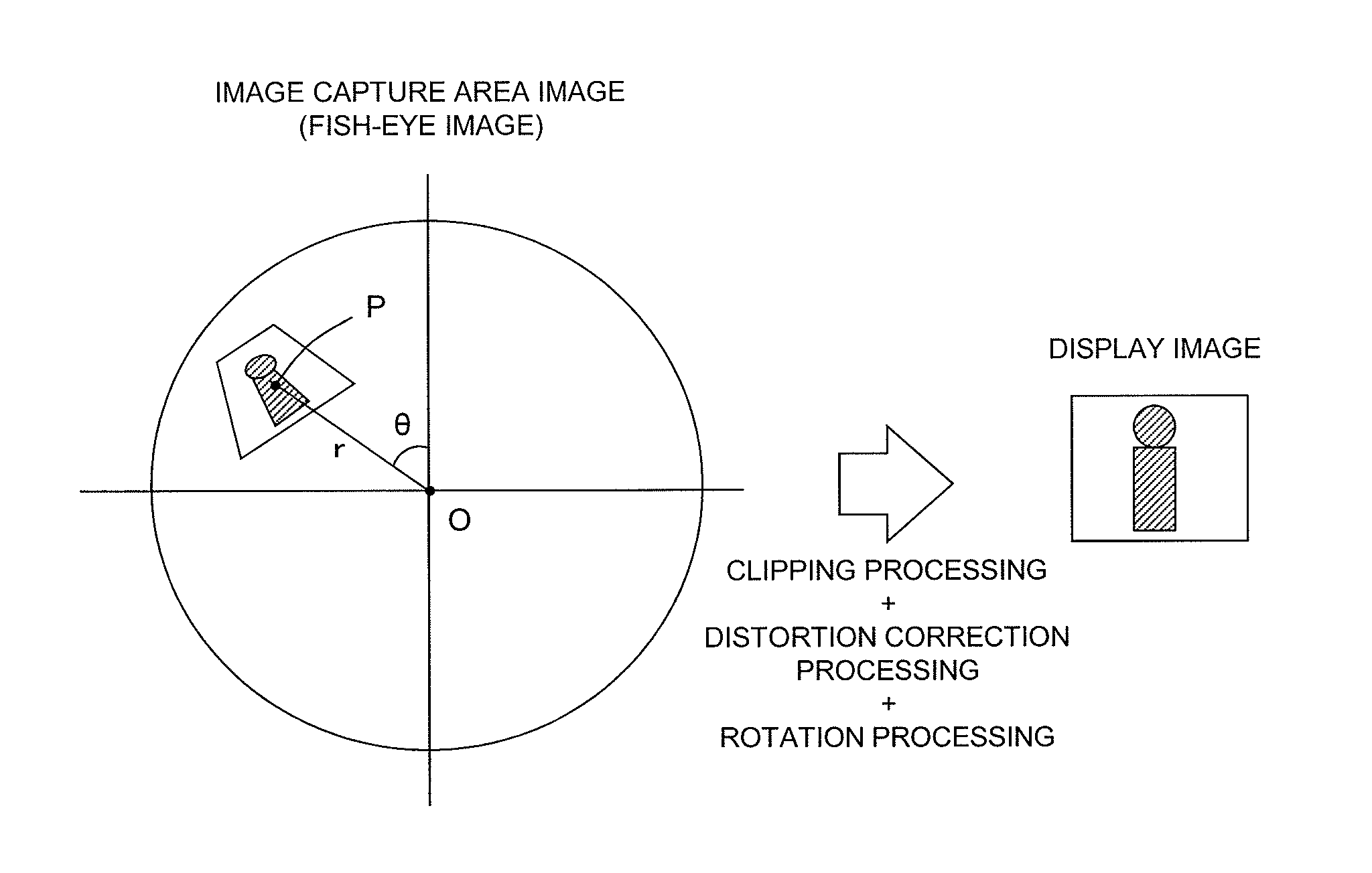
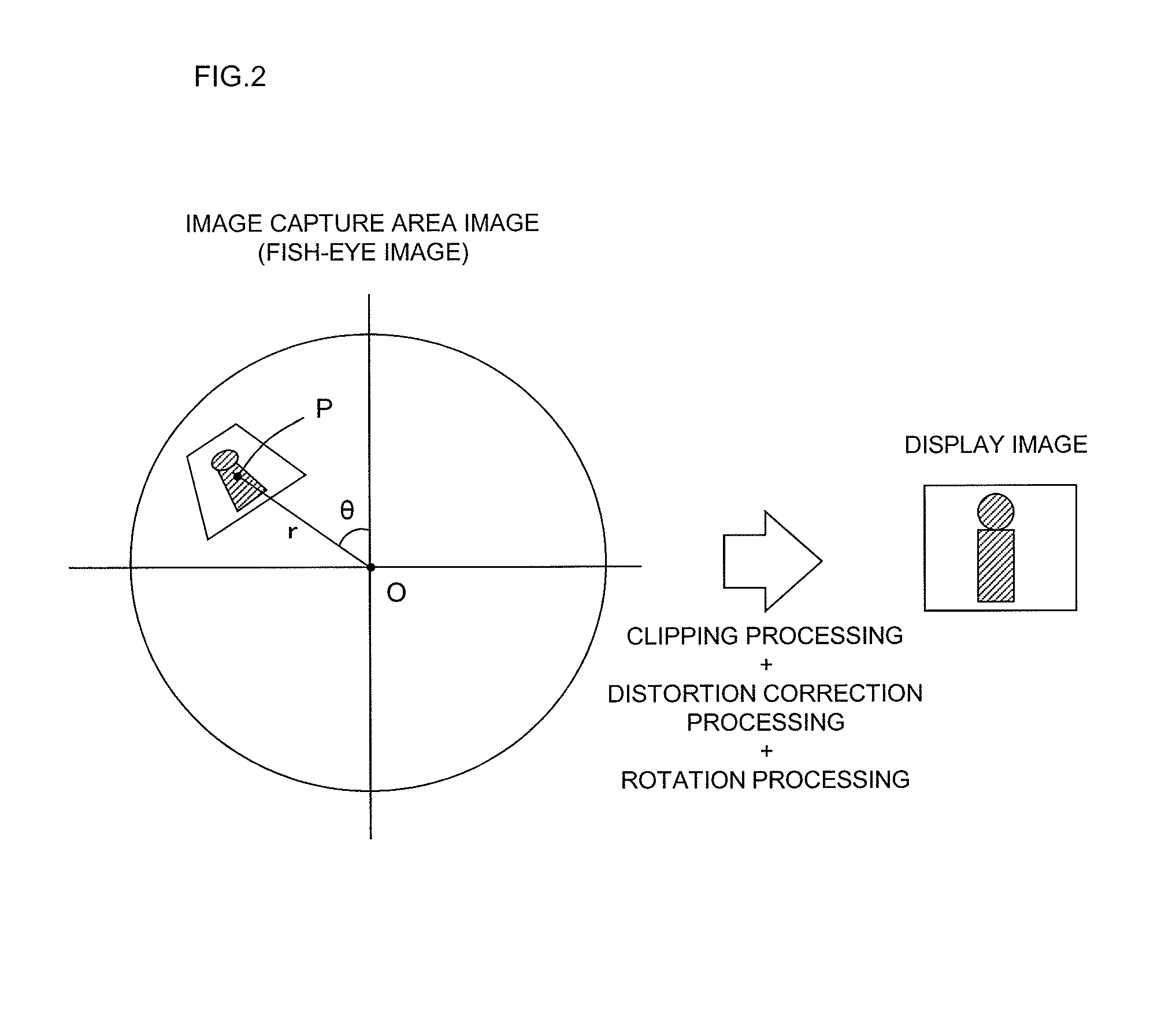
[0048]The imaging unit 2 has an imaging element (not shown) such as a CCD or a CMOS and a lens (not shown) disposed on the light axis of the imaging. The lens of the imaging unit 2 is a lens having a wider angle of view than a normal lens (for example, a fish-eye lens, a quasi wide-angle lens, a wide-angle lens, and a super wide-angle lens). The imaging unit 2 is installed on, for example, a ceili...

second embodiment

[0068]Next, a camera device in accordance with a second embodiment of the present invention will be described. Here, differences of the camera device of the second embodiment from the first embodiment will be mainly described. Unless otherwise noted, the configuration and the operation of the embodiment are the same as those of the first embodiment.

[0069]FIG. 6 is a block diagram showing a configuration of a camera device 1 in accordance with the second embodiment. As shown in FIG. 6, a display-image generation unit 3 has a virtual-reference-position determination unit 11. The virtual-reference-position determination unit 11 determines, based on an clipping reference position P, a virtual clipping reference position P′ having a distance r from an imaging reference position O of not shorter than a radius c when an imaging object included in an imaging area image is within a predetermined specific region (for example, a circle area with a center of the imaging reference position O and...


PUM


Abstract

A camera device includes an imaging unit generating an imaging area image in which an imaging area is captured from above, and a display-image generation unit generating a display image of an imaging object moving in the imaging area by use of an clipped image clipped from the imaging area image. In this case, an clipping reference position P corresponding to the imaging object in the imaging area image is determined, and a reference distance r between an imaging reference position O corresponding to the imaging unit and the clipping reference position P in the imaging area image is calculated. When the reference distance r is short, a rotation angle θNEW for rotating the clipped image in generating the display image is calculated based on a reference angle θ corresponding to an inclination of the imaging object in the imaging area image and the reference distance r.

Description

TECHNICAL FIELD[0001]The present invention relates to a camera device having a function of generating a display image of an imaging object moving in an imaging area by use of an clipped image clipped from an image (imaging area image) in which the imaging area is captured from above.BACKGROUND ART[0002]Conventionally, a system that generates a display image by processing an omni-directional image (fish-eye image) captured by a camera having a fish-eye lens has been proposed (for example, refer to Patent Literature 1 to Patent Literature 3). As one of such image processing systems, a system is known in which a display image of an imaging object moving in an imaging area is generated by using an clipped image clipped from an image (imaging area image) in which the imaging area is captured from above.[0003]In the conventional system like this, since the imaging area image is captured by the camera having the fish-eye lens, the imaging object inclines according to the position of the im...

Claims


Application Information

Patent Timeline
IPC IPC(8): H04N5/262
CPCH04N5/23293H04N5/217G06T3/60H04N5/2621H04N5/2628H04N23/81H04N23/63
Inventor TSUBOTA, KAZUHIROKUWADA, JUNYA
Owner PANASONIC CORP
Why Eureka
Try Eureka