Lens array unit, erecting equal-magnification lens array, optical scanning unit, image reading device, and image writing device

a technology of equal-magnification lens array and array unit, which is applied in the direction of instruments, optics, electrographic process apparatus, etc., can solve the problems of large number of components, high array cost, and noise generation as it leaves

Active Publication Date: 2013-08-29
NIPPON SHEET GLASS CO LTD
View PDF3 Cites 18 Cited by
  • Summary
  • Abstract
  • Description
  • Claims
  • Application Information

AI Technical Summary

Benefits of technology

[0010]The present invention addresses the aforementioned disadvantage and a purpose thereof is to provide an inexpensive len

Problems solved by technology

Therefore, there is a problem in that a light beam diagonally incident on the erecting equal-magnification lens array travels diagonally inside the plate and enters an adjacent convex lens, creating noise (referred to as ghost noise) as

Method used


Image

  • Lens array unit, erecting equal-magnification lens array, optical scanning unit, image reading device, and image writing device
  • Lens array unit, erecting equal-magnification lens array, optical scanning unit, image reading device, and image writing device
  • Lens array unit, erecting equal-magnification lens array, optical scanning unit, image reading device, and image writing device

Examples


first embodiment

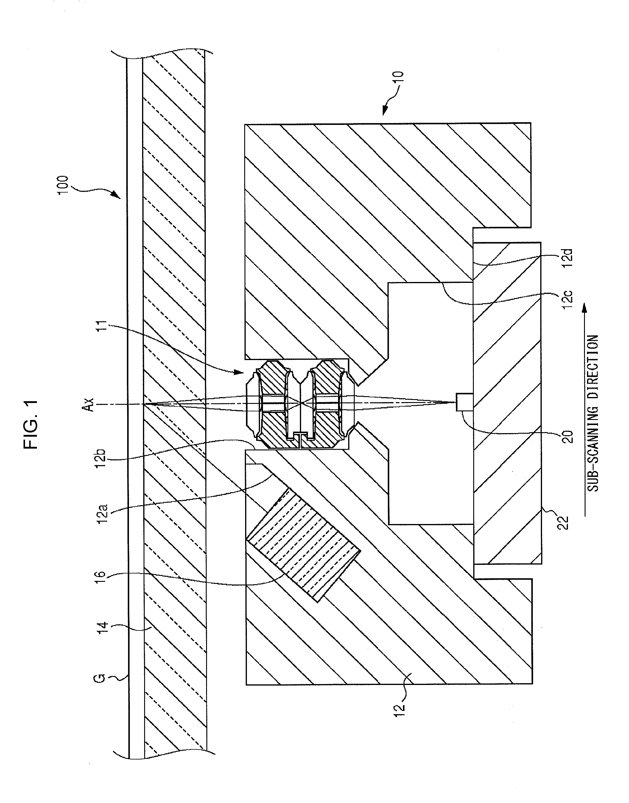
[0059]FIG. 1 shows an image reading device 100 in which the lens array unit according to the present invention is used. As shown in FIG. 1, the image reading device 100 comprises an optical scanning unit 10, a glass plate 14 on which a document G is placed, a driving mechanism (not shown) for driving the optical scanning unit 10, and an image processing unit (not shown) for processing data read by the optical scanning unit 10.

[0060]The optical scanning unit 10 comprises a linear light source 16 for illuminating a document G placed on the glass plate 14, an erecting equal-magnification lens array 11 for condensing light reflected from the document G, a linear image sensor (photoelectric transducer) 20 for receiving light condensed by the erecting equal-magnification lens array 11, and a housing 12 for housing the linear light source 16, the erecting equal-magnification lens array 11, and the linear image sensor 20.

[0061]The housing 12 is substantially cuboid in shape. A first recess ...

third embodiment

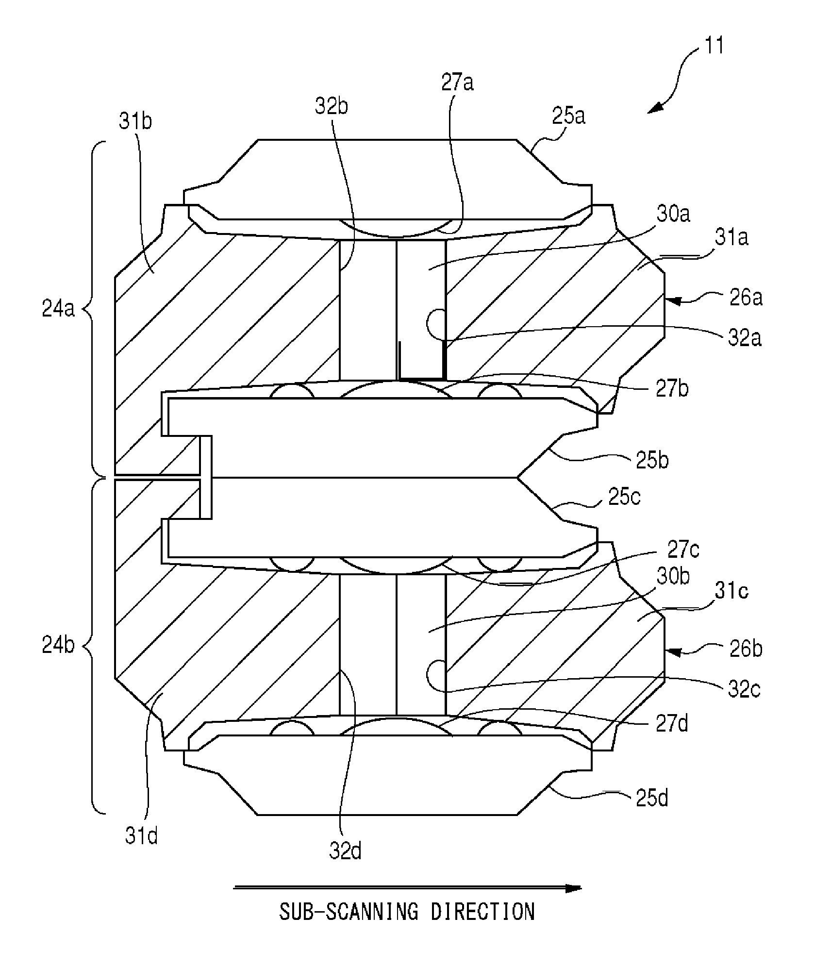
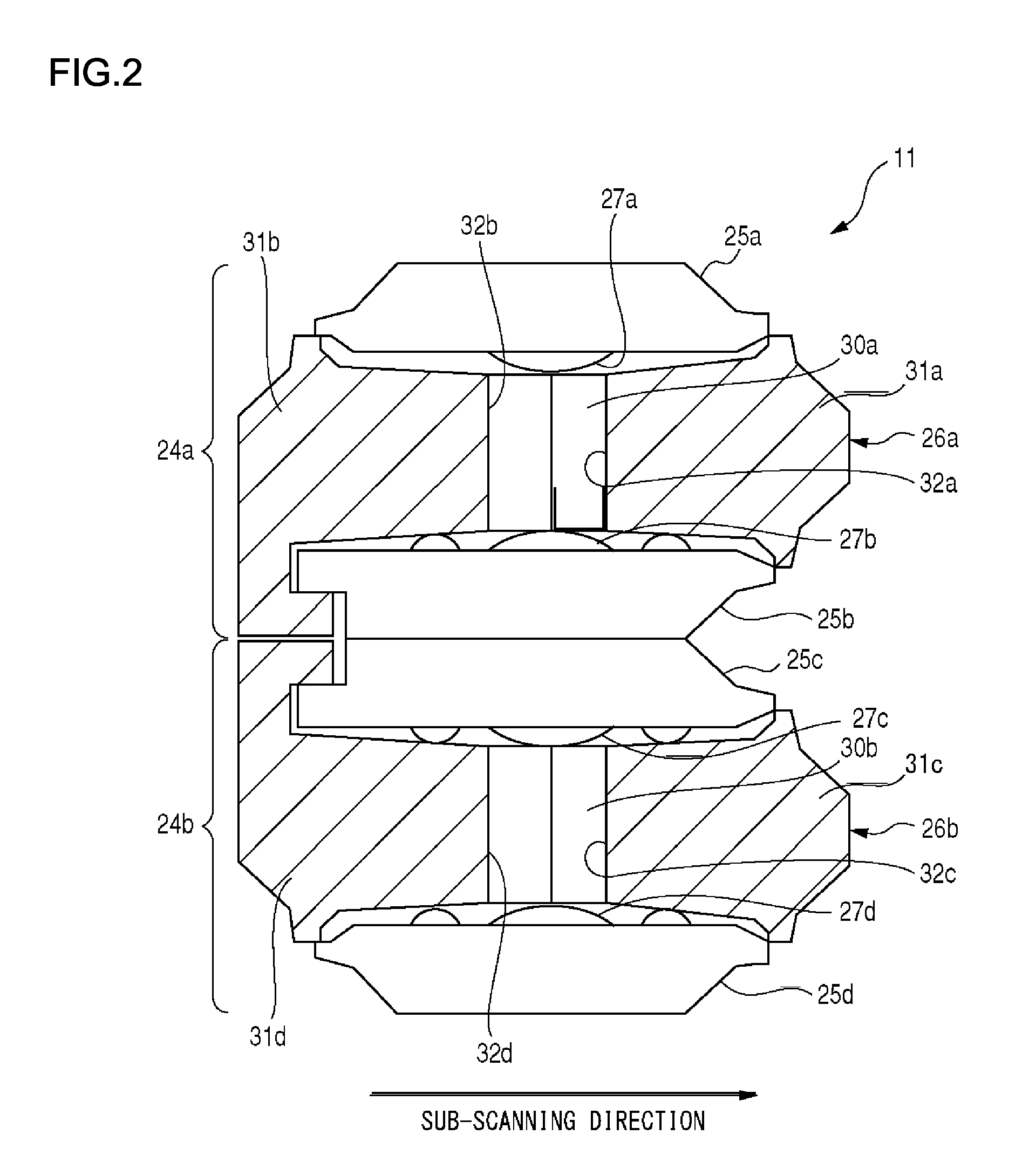
[0103]As shown in FIG. 7, an erecting equal-magnification lens array 70 comprises a stack of a first lens array plate 71, a second lens array plate 72, and a third lens array plate 73. A first light shielding member 74 is provided between the first lens array plate 71 and the second lens array plate 72, and a second light shielding member 75 is provided between the second lens array plate 72 and the third lens array plate 73.

[0104]The first lens array plate 71 is a rectangular plate. A linear arrangement of a plurality of first lenses 71a is formed on one surface (bottom surface) of the plate 71 in the main scanning direction. The first light shielding member 74 is provided with a plurality of first through holes 76 formed in the main scanning direction. The first light shielding member 74 includes a first light shielding member piece 74a and a second light shielding member piece 74b produced by splitting the member 74 by a splitting plane through the centers of the plurality of fi...

fifth embodiment

[0118]In the fifth embodiment, the first and second light shielding members 74 and 75 are split by a plane parallel to the sub-scanning direction. In other words, the first light shielding member 74 is split into a first light shielding member piece 105 and a second light shielding member piece 106, and the second light shielding member 75 is split into a third light shielding member piece 107 and a fourth light shielding member piece 108. A first through hole piece 95 is formed in the first light shielding member piece 105, a second through hole piece 96 is formed in the second light shielding member piece 106, a third through hole piece 97 is formed in the third light shielding member piece 107, and a fourth through hole piece 98 is formed in the fourth light shielding member piece 108. The splitting plane may not necessarily be parallel to the sub-scanning direction so long as the plane intersects the central axes of a plurality of through holes.

[0119]In the fifth embodiment, the...


PUM


Abstract

A first lens array unit includes a first lens array plate and a second lens array plate in which a plurality of lenses are provided in the main scanning direction, and a first light shielding member piece and a second light shielding member piece provided with a plurality of through holes corresponding to the lenses. The first lens array plate, the second lens array plate, the first light shielding member piece, and the second light shielding member piece are formed as one piece. The lens array is built by bending joints joining the lens array plates and the light shielding member pieces such that the lens is located to directly face the corresponding through hole.

Description

BACKGROUND OF THE INVENTION[0001]1. Field of the Invention[0002]The present invention relates to lens array units used in image reading devices and image forming devices.[0003]2. Description of the Related Art[0004]Some image reading devices such as scanners are known to use erecting equal-magnification optics. Erecting equal-magnification optics are capable of reducing the size of devices better than reduction optics. In the case of image reading devices, an erecting equal-magnification optical system comprises a linear light source, an erecting equal-magnification lens array, and a linear image sensor.[0005]In the related art, a rod lens array capable of forming an erect equal-magnification image is used as an erecting equal-magnification lens array in an erecting equal-magnification optical system. Recently, however, there is proposed an erecting equal-magnification lens array plate comprising a stack of two transparent lens array plates built such that the optical axes of indivi...

Claims


Application Information

Patent Timeline
IPC IPC(8): G02B27/10
CPCG03G15/04054G02B3/0075G03G15/0435G03G15/04036G03G15/041G02B3/0062G02B3/0037G02B3/0068G03G15/0409G02B3/005
Inventor NEMOTO, HIROYUKI
Owner NIPPON SHEET GLASS CO LTD
Why Eureka
Try Eureka